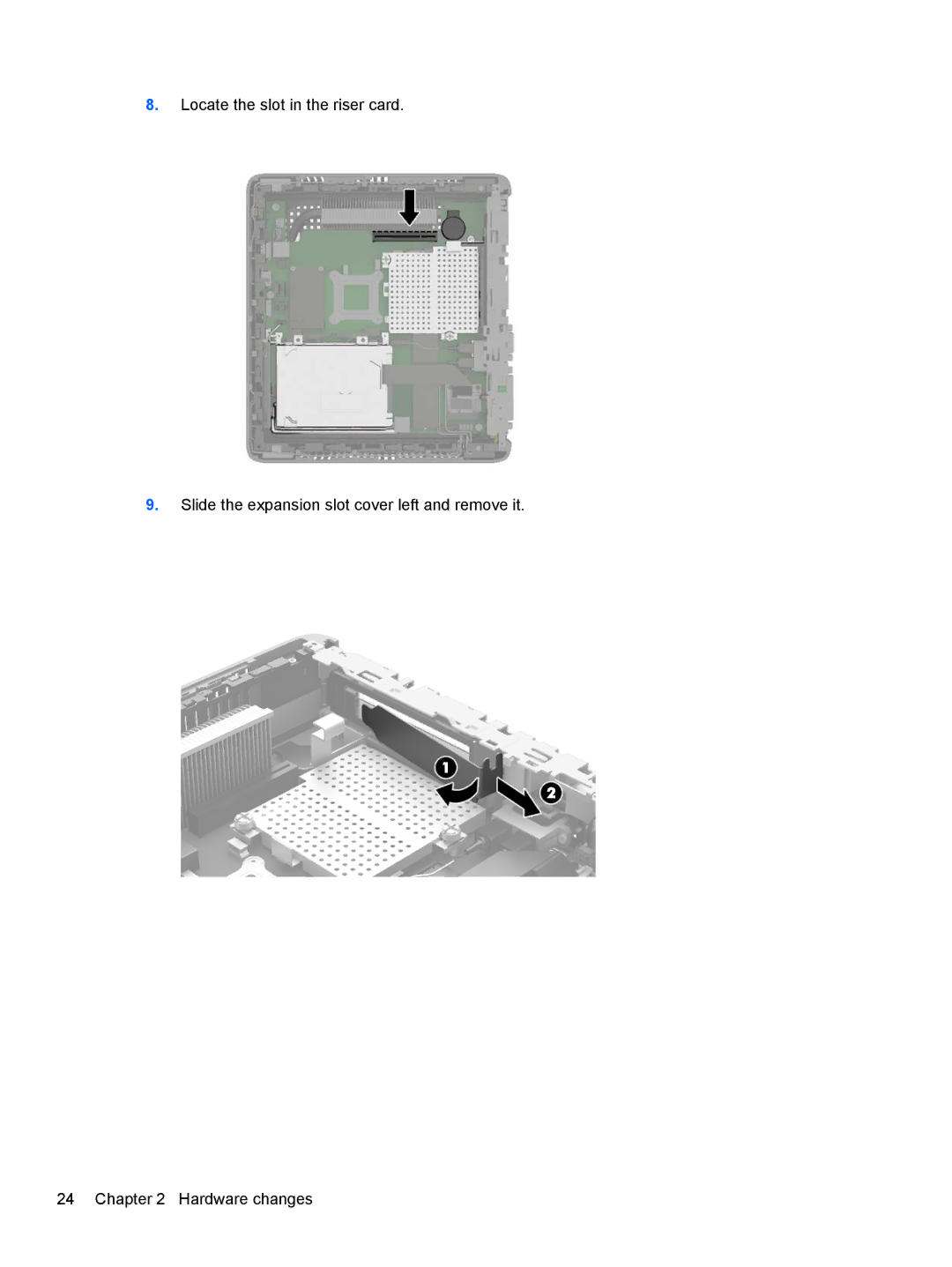
Manuals
/
HP
/
Computer Equipment
/
Laptop
HP
ZBook 14 Mobile manual Locate the slot in the riser card, Hardware changes
Models:
ZBook 14 Mobile
1
30
53
53
Download
53 pages
32.2 Kb
27
28
29
30
31
32
33
34
<
>
Specification
Install
Connecting the power cord
Appendix B Removing and replacing the battery
Reconnect the power cord and turn on the computer
Important service repair information
Removing and replacing the access panel
Product features
Using the keyboard
Page 30
Image 30
8.
Locate the slot in the riser card.
9.
Slide the expansion slot cover left and remove it.
24 Chapter 2 Hardware changes
Page 29
Page 31
Page 30
Image 30
Page 29
Page 31
Contents
Hardware Reference Guide
HP t620 Flexible Series Thin Client
Hardware Reference Guide
About This Book
iv About This Book
Appendix A Specifications
Table of contents
1 Product features
2 Hardware changes
Appendix D Electrostatic discharge
Appendix B Removing and replacing the battery
Appendix C Thin client operation
Appendix E Shipping information
1 Product features
Standard features
Front panel components
Rear panel components
Scroll Lock key
Using the keyboard
Caps Lock key
Num Lock key
Special mouse functions
Windows Logo Key
Additional function keys
Serial number location
6 Chapter 1 Product features
2 Hardware changes
Warnings and cautions
Connecting the power cord
Attaching the stand
Removing and replacing the access panel
Removing the access panel
Removing and replacing the access panel
5. Remove the computer from the stand
6. Lay the unit flat on a stable surface with the right side up
Replacing the access panel
To replace the access panel
12 Chapter 2 Hardware changes
Removing and replacing the access panel
Installing internal USB flash drives
Installing additional memory
SODIMMs
DDR3L-SDRAM SODIMMs
Installing SODIMMs
Populating SODIMM sockets
on page
18 Chapter 2 Hardware changes
Installing additional memory
8. Locate the memory compartment on the system board
NOTE Be sure to retain the two screws and the springs beneath them
20 Chapter 2 Hardware changes
Installing additional memory
19. Replace the computer stand
20. Reconnect the power cord and turn on the computer
22 Chapter 2 Hardware changes
Installing a half-height PCI-Express 2.0 card
8. Locate the slot in the riser card
9. Slide the expansion slot cover left and remove it
24 Chapter 2 Hardware changes
14. Reconnect the power cord and turn on the computer
Installing a half-height PCI-Express 2.0 card
13. Replace the computer stand
Security
Hood sensor
Cable lock
1. Locate the cable lock slot on the back panel
Security
Mounting the thin client
30 Chapter 2 Hardware changes
Supported mounting options
Mounting the thin client
Dimensions
A Specifications
32 Appendix A Specifications
Temperature Range fanless design
Maximum Altitude unpressurized
Power Supply
Power Output maximum
Rated Output Current maximum
B Removing and replacing the battery
b. If a PCIe card is installed, remove it carefully
2 up and out of the way
10. Unplug the battery cable connector from the system board
8. Locate the battery on the system board
9. Carefully pry the battery up from the system board
36 Appendix B Removing and replacing the battery
15. Replace the computer stand
C Thin client operation
Routine thin client care
Supported orientations
40 Appendix C Thin client operation
Non-supported orientation
D Electrostatic discharge
Preventing electrostatic damage
Grounding methods
Shipping preparation
Important service repair information
E Shipping information
Removing the solid state drive flash memory
8. Remove the two screws securing the SSD to the system board
44 Appendix E Shipping information
Important service repair information
9. Carefully pull the SSD out of the socket
Index
K keyboard