14. COMMON INTERFACE
![]()
![]()
![]()
![]()
![]()
![]() 15. SMARTCARD SLOT
15. SMARTCARD SLOT
![]()
![]()
![]() 9. S/PDIF
9. S/PDIF
![]()
![]()
![]() 10. H/P (Headphone)
10. H/P (Headphone) ![]()
![]()
![]()
![]()
![]()
![]()
![]()
![]()
![]()
![]()
![]() Red3 : AUDIO : R
Red3 : AUDIO : R ![]()
![]()
![]()
![]() White : AUDIO : L
White : AUDIO : L ![]()
![]()
![]()
![]()
![]() Yellow : VIDEO
Yellow : VIDEO
![]()
![]()
![]() 12.
12.
![]()
![]()
![]() Red2 : AUDIO : R
Red2 : AUDIO : R ![]()
![]()
![]()
![]() White : AUDIO : L
White : AUDIO : L ![]()
11. AV 4 (RCA) |
16. MAIN POWER
Red1 : Pr
13. COMPONENT |
![]()
![]()
![]() Blue : Pb
Blue : Pb
![]()
![]()
![]() Green : Y
Green : Y
![]()
![]() 75
75
AC INPUT 1 |
|
|
DVI INPUT 2 |
|
|
PC INPUT 3 |
|
|
AUDIO INPUT 4 |
|
|
|
| |
USB MASTER PORT 6 | AV1 7 | AV2 7 AV3 7 ANT IN 8 |
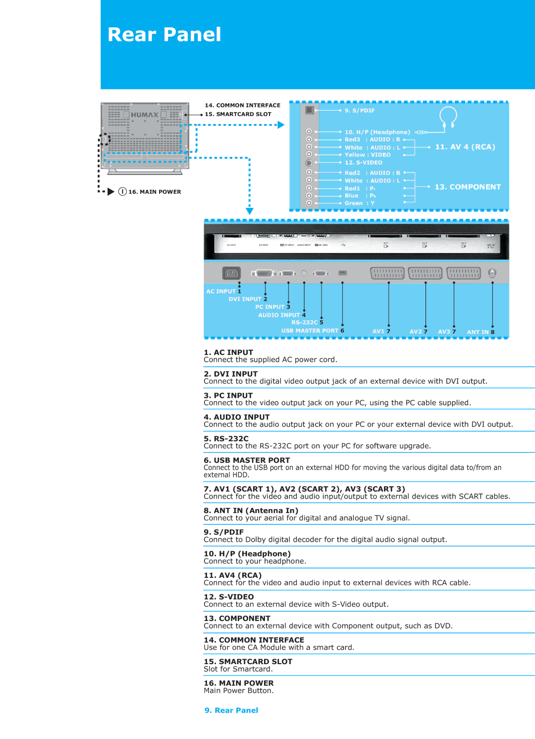
1. AC INPUT
Connect the supplied AC power cord.
2. DVI INPUT
Connect to the digital video output jack of an external device with DVI output.
3. PC INPUT
Connect to the video output jack on your PC, using the PC cable supplied.
4. AUDIO INPUT
Connect to the audio output jack on your PC or your external device with DVI output.
5. RS-232C
Connect to the
6. USB MASTER PORT
Connect to the USB port on an external HDD for moving the various digital data to/from an external HDD.
7. AV1 (SCART 1), AV2 (SCART 2), AV3 (SCART 3)
Connect for the video and audio input/output to external devices with SCART cables.
8. ANT IN (Antenna In)
Connect to your aerial for digital and analogue TV signal.
9. S/PDIF
Connect to Dolby digital decoder for the digital audio signal output.
10.H/P (Headphone)
Connect to your headphone.
11.AV4 (RCA)
Connect for the video and audio input to external devices with RCA cable.
12.
Connect to an external device with
13. COMPONENT
Connect to an external device with Component output, such as DVD.
14. COMMON INTERFACE
Use for one CA Module with a smart card.
15.SMARTCARD SLOT Slot for Smartcard.
16.MAIN POWER Main Power Button.
9. Rear Panel