EM78P809N
DOC. Version
Elan Microelectronics Corporation
Contents
Specification Revision History
CPU
Bit Microcontroller
Applications
„ General purpose
Pin Assignment
OTP Programming Pins
Functional Block Diagram
Function Description
Operating Registers
Tbktc
R1/TCC − Time Clock /Counter Address 01h
R2/PC − Program Counter & Stack Address 02h
Bit 5 Not used
R3/SR − Status Register Address 03h
Bit 7 ~ Bit 6 RBS1 ~ RBS0 R-Register page select
RBS1 RBS0
Bit 0 C Carry flag R4/RSR − RAM Select Register Address 04h
GRBS1 GRBS0
General Purpose Register Bank Address 20H ~ 3FH
PORT7 Port 7 I/O Data Register Address 07h
SIS = 0 Idle mode SIS = 1 Sleep mode
PORT6 − Port 6 I/O Data Register Address 06h
PORT8 − Port 8 I/O Data Register Address 08h
TC4FF1 TC4FF0
TC4CR Timer/Counter 4 Control Register Address 0Bh
TC4S = 1 Start
TC4CK2 TC4CK1 TC4CK0
Bit Microcontroller TC4D − Timer 4 Data Buffer Address 0Ch
ISFR1 − Interrupt Status Flag Register 1 Address 0Eh
TC3S = 1 Start
Bit 7 TC3CAP Software capture control
TC3CAP =
TC3CAP TC3S TC3CK1 TC3CK0 TC3M
Bit 7 ~ Bit 6 ADD1 ~ ADD0 AD low 2-bit data buffer
TC3DB − Timer 3 Data Buffer B Address 07h
TC2M = 1 Window mode
TC2S = 1 Start
TC2DH − Timer 2 Data Buffer High Byte Address 09h
TC2DL − Timer 2 Data Buffer Low Byte Address 0Ah
Adcr − AD Control Register Address 0Bh
Adic − AD Input Pin Control Address 0Ch
Bit 3 ADP AD power control
Bit 7 ~ Bit 0 ADE7 ~ ADE0 AD input pin enable control
Addh − AD High 8-bit Data Buffer Address 0Dh
Bit 3 Tbten Time Base Timer Enable Control
Bit 7 TEN Keytone enable control
TEN = 0 Disable TEN = 1 Enable
Bit Microcontroller Tbktc − TBT/Keytone Control Address 0Eh
Uinven = 1 Enable TXD and RXD port inverse output
Bit 3 Uinven Enable Uart TXD and RXD port inverse output
Uinven = 0 Disable TXD and RXD port inverse output
Bit 4 ~ Bit 2 BRATE2 ~ BRATE1 Transmit Baud Rate Select
Bit 5 PRE Enable parity addition
Bit Microcontroller URS − Uart Status Register Address 07h
Even = 0 Odd parity Even = 1 Even parity
SMP Dcol BRS2 BRS1
Bit 2 EDS Data shift out edge select
EDS = 0 Rising edge EDS = 1 Falling edge
EDS Dord WBE
Spid SPI Data Buffer Address 07h
Transfer Mode
SPIC2 − SPI Control Register 2 Address 06h
SPID7 SPID6 SPID5 SPID4 SPID3 SPID2 SPID1 SPID0
PHC2 − Pull High Control Register 2 Address 0Ch
PLE7x = 1 Disable P7x pull low
PLC1 Pull Low Control Register 1 Address 0Bh
PLC2 − Pull Low Control 2 Address 0Dh
Control Register
Special Purpose Registers
Accumulator
Bit 7 Wdto WDT output select
Bit 2 Reserved
Bit Microcontroller IOC6 ~ IOC9 − I/O Port Control Register
Intcr − INT Control Register Address 0Bh
INT1ES = 0 Rising edge INT1ES = 1 Falling edge
Adoscr − AD Offset Control Register Address 0Ch
INT Pin Secondary Enable Condition Function Pin
External Interrupt
Edge
IMR2 − Interrupt Mask Register 2 Address 0Fh
Uerrie Urie Utie Tbie EXIE1 TCIE0
Rbank Register Bank bits 7, 6 of R3, R/W Read/Write
CPU Operation Mode
Registers for CPU operation mode
Rbank
Mode Switching Control
Operation Mode
Normal
AD Converter
→ Don’t care → Interrupt request flag will be recorded
Registers for AD Converter Circuit
ADC Data Register
Sampling Time
Conversion Time
Time Base Timer and Keytone Generator
ADCK10
Max. Frequency Max. Conversion Rate per Bit
Tone Output Pin Timing Chart
Uart Universal Asynchronous Receiver/Transmitter
Registers for Uart Circuit
Rbank Address Name Bit 7 Bit 6 Bit 5 Bit 4 Bit 3 Bit 2 Bit
Uart Mode
Data Format in Uart
Transmitting
Receiving
SPI Serial Peripheral Interface
Baud Rate Generator
Registers for the SPI Circuit
Bit Transmit Mode
Shift Direction and Sample Phase
Transfer Mode
Serial Clock
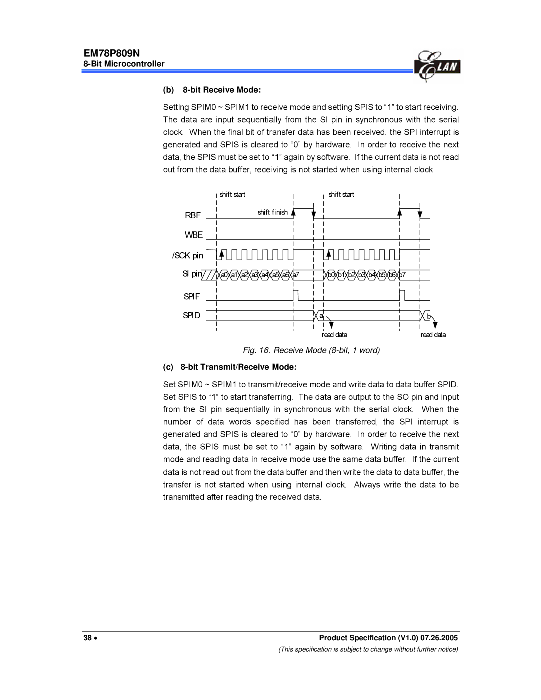
Bit Microcontroller Bit Receive Mode
Bit Transmit/Receive Mode
SCK pin
Multiple Device Connect /SS
Timer/Counter
Registers for Timer/Counter 2 Circuit
Rbank Address Name Bit 7 Bit 6 Bit
Timer Mode
Counter Mode
Window Mode
Window Mode Timing Chart
Registers for Timer/Counter 3 Circuit
Capture mode
Configuration of Timer/Counter3
Registers for Timer 4 Circuit
TCIF4
PDO Mode
TCR4
PWM Mode
12 TCC/WDT & Prescaler
TC4 Interrupt
Reset and Wake-up
Reset
13 I/O Ports
Wake-up from Sleep Mode
Wake-up from Idle mode
All interrupt
Address Name Reset Type Bit
Summary of the Initialized Values for Registers
Bit Microcontroller Register Bank
SCR
TC2D9 TC2D8
Register Bank
Status of RST, T, and P of Status Register
Previous value before reset
Reset Type
Bit Microcontroller General Purpose Registers
Controller Reset Block Diagram
Interrupt
Crystal Oscillator/Ceramic Resonators Crystal
Oscillator
Oscillator Modes
Summary of Maximum Operating Speeds
Ext. Clock
Oscillator Type Frequency Mode C1 pF C2 pF
EM78P809N
740
External RC Oscillator Mode
Crystal/Resonator-Parallel Mode Circuit
Code Option Register Word
Enwdtb = 0 Enable Enwdtb = 1 Disable
Code Option Register
For design reference only
Customer ID Register
Power-on Considerations
External Power-on Reset Circuit
Cyes = 0 One cycle Cyes = 1 Two cycles
EM78P809N Rin
Residue-Voltage Protection
Vdd
Vdd EM78P809N
Instruction Set
Vdd 40KR2
Binary Instruction Hex Mnemonic Operation Status Affected
DEC
Recommended Operating Conditions
Symbol Parameter Condition Min Typ Max Unit
Absolute Maximum Ratings
Vss =
DC Electrical Characteristics
Ta= 25 C, VDD= 5.0V ± 5%, VSS=
Typical value is based on characterization results at 25C
Ta= 25 C, VDD= 3.0V ± 5%, VSS=
Varef
Ta=- 40C ~ 85 C, VDD=5V ± 5%, VSS=0V
AC Electrical Characteristic
Symbol Parameter Conditions Min Typ Max Unit
= selected prescaler ratio
Timing Diagram
AC Test Input/Output Waveform
Package Types
OTP MCU
Pin Count Package Size
Contents III
EM78P809N