Version 1.0 06/2001
User Manual Part 1 I-8090 3-axis encoder card
Part 2 I-8091 2-axis stepping/servo control card
I-8090/I-8091 User Manual
I-8090/I-8091 User ManualVersion 1.0 06/2001
I-8090 Contents
I-8091 Contents
Version 1.0 06/2001 Edition
I-8090 3-axis encoder card User Manual
Copyright Copyright 2001 by ICP DAS. All right are reserved Trademark
I-8090 3-axis encoder card
Features
8090 Contents
1.1 I-8000 hardware address
1. Hardware
I-8000, 4 slots I-8000, 8 slots
1.2 Registers of I-8090 board
Quadrant Counting Mode
counter
Fig3 CW/CCW counting mode 10 Pulse/Direction counting mode
I-8090 User Manual
1.3 LED Indicator
power
1C 2A
1.4 Connection
Encoder
06/2001
Encoder
I-8090 User Manual
Version
S8090 card
I-8090 User Manual
S8091 card
Version 1.0 06/2001
Functions
2. Software
2.1 constants and functions
Constants
address hardware address which defined at chapter
5 unsigned char i8090GETINDEXunsigned char cardNo
4 void i8090RESETENCODERunsigned char cardNo, unsigned char axis
8 long i8090GETENCODER32unsigned char cardNo, unsigned char axis
32 bits encoder counts command sets
7 void i8090RESETENCODER32unsigned char cardNo, unsigned char axis
6 void i8090ENCODER32ISRunsigned char cardNo
2.2 examples
2.2.3 Get X, Y, Z-axis encoder counter’s value
case Yaxis
2.2.4 Software 32 bits encoder counter programming
#define CARD1 1 #define CARD2 2 #define MAXSLOTNO
Show5DigitLed0x04, j value=value/10 j=value-10*value/10
break default
int key,ShowAxis i8090Slot=99 for j=0 jMAXSLOTNO j++
Delay5 //delay 5ms
case 2 ShowLedValuezvalue,Zaxis break
switch ShowAxis
case 0 ShowLedValuexvalue,Xaxis break
case 1 ShowLedValueyvalue,Yaxis break
Version 1.0 06/2001 Edition
I-8091 2-axis stepping/servo motor control card User Manual
Copyright Copyright 2001 by ICP DAS. All right are reserved Trademark
Features
I-8091 2-axis Stepping/Servo Motor Control Card
I-8091 Contents
1. Introduction
1.1 System Block Diagram
1.2 DDA Technology
Example Stepping Motor
Example Pulse type input Servo Motor
2.1 I-8000 hardware address
2 Hardware
I-8000, 4 slots I-8000, 8 slots
2.2 Registers of I-8091 board
2.3 LED Indicator
Y axis
2.4 Hardware Configuration 2.4.1 Limit switch configuration
2.4.5 Automatic protection
2.4.2 Output pulse mode configuration
2.4.3 Direction configuration
2.4.4 Turn Servo ON/OFF Hold ON/OFF
2.4.6 Set limit switch as normal close condition
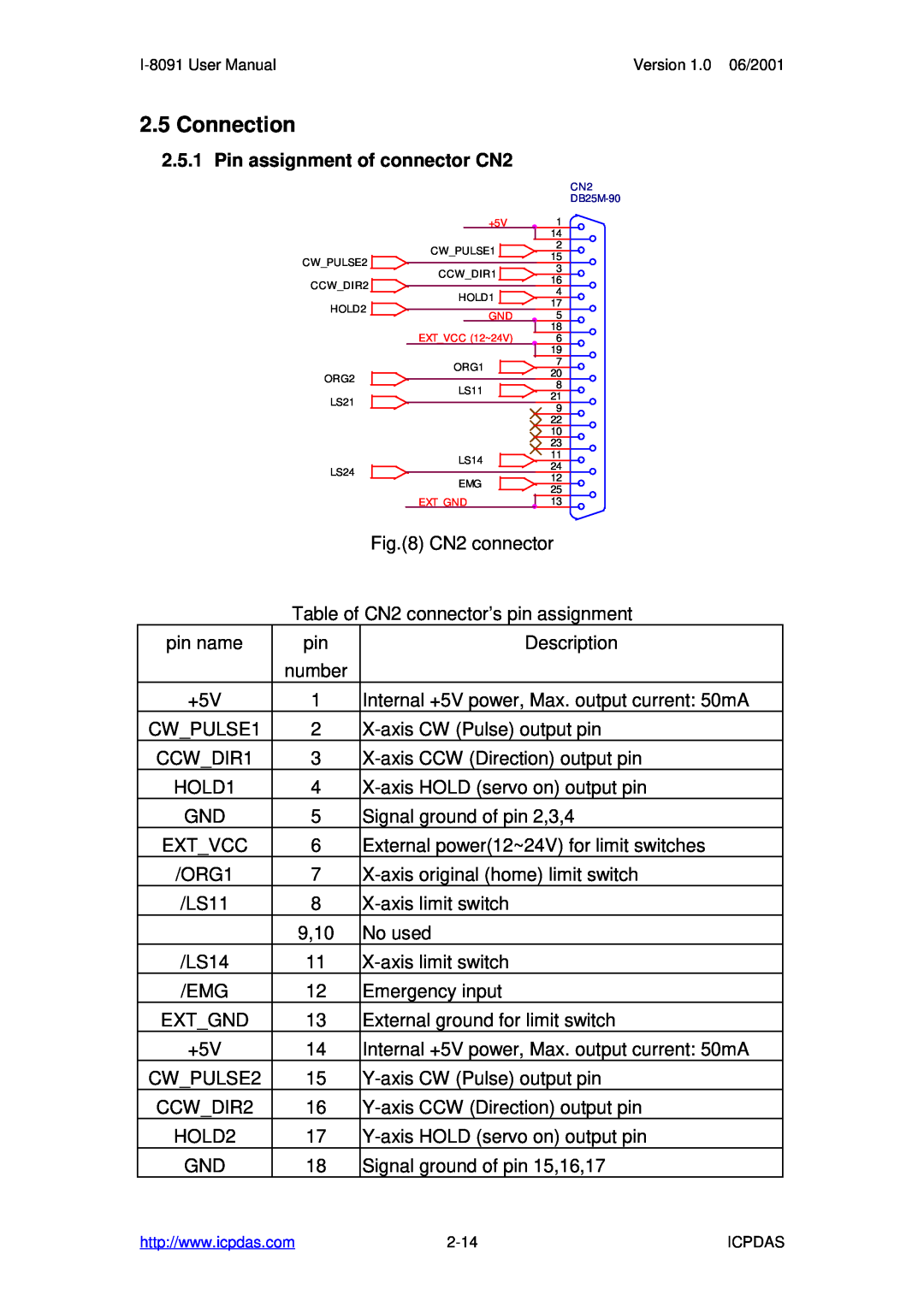
2.5 Connection
2.5.1 Pin assignment of connector CN2
2.5.3 The internal circuit of limit switch input
2-16
2.5.4 Example of connection
I-8091 User Manual
Version 1.0 06/2001
2-17
I-8091 User Manual
Version 1.0 06/2001
S8090 card
3.1 Functions
3. Software
Constants
ICPDAS
I-8091 User Manual
Version 1.0 06/2001
2-19
LowSpeed
3.1.1 Setting commands
2 i8091RESETSYSTEM unsigned char cardNo
unsigned int
LowSpeed = AccDec
DDA cycle≤
Low Speed ≤
High Speed≤
unsigned char sonX, unsigned char sonY
5 i8091SETMODEunsigned char cardNo, unsigned char modeX
unsigned char modeY
6 i8091SETSERVOONunsigned char cardNo
sw 0NO
Limit switches ORG1, LS11, LS14, ORG2, LS21, LS24, EMG
normal open default
cardNo card number 0~19
11 i8091EMGSTOPunsigned char cardNo
3.1.2 Stop Commands
14 i8091LSPPULSEMOVEunsigned char cardNo
3.1.3 Simple motion commands
12 i8091LSPORGunsigned char cardNo
unsigned char DIR, unsigned char AXIS
unsigned char DIR, unsigned char AXIS
15 i8091HSPPULSEMOVEunsigned char cardNo
16 i8091LSPMOVEunsigned char cardNo
unsigned char AXIS, long pulseN
high speed
17 i8091HSPMOVEunsigned char cardNo
unsigned char DIR, unsigned char AXIS
Low speed
command i8091STOPX, i8091STOPY, i8091STOPALL, or i8091SLOWSTOP
ICPDAS
I-8091 User Manual
Version 1.0 06/2001
2-29
− 2047≤ # Xpulse≤ − 2047≤ #Ypulse≤
3.1.4 Interpolation commands
23 i8091INTPLINE02unsigned char cardNo, long x, long y
#Ypulse≤
unsigned int speed unsigned char accmode
Y X,Y CW X CCW where r adius = sqr tX2 + Y2
R ≥
#≤ x 2−
#≤ y 2−
#≤ R 2−
i8091INTPLINE02, i8091INTPCIRCLE02 and
26 unsigned char i8091INTPSTOP
3.1.5 Others
Page
Start up program
i8091RESETSYSTEMCARD1
end of program i8091RESETSYSTEMCARD1
3.2 Start up and end of program
2-38
Version 1.0 06/2001
ICPDAS
4.1 Detect I-8091 card
4. Example
2-40
4.2 Example DEMO.cpp
4.3 ExampleDEMO1.cpp
Version 1.0 06/2001