SentinelRAID 170 Installation and Hardware Reference Manual
upgrade sockets allow for the installation of a daughter board that facilitates the addition of four
The controller board also comes with a
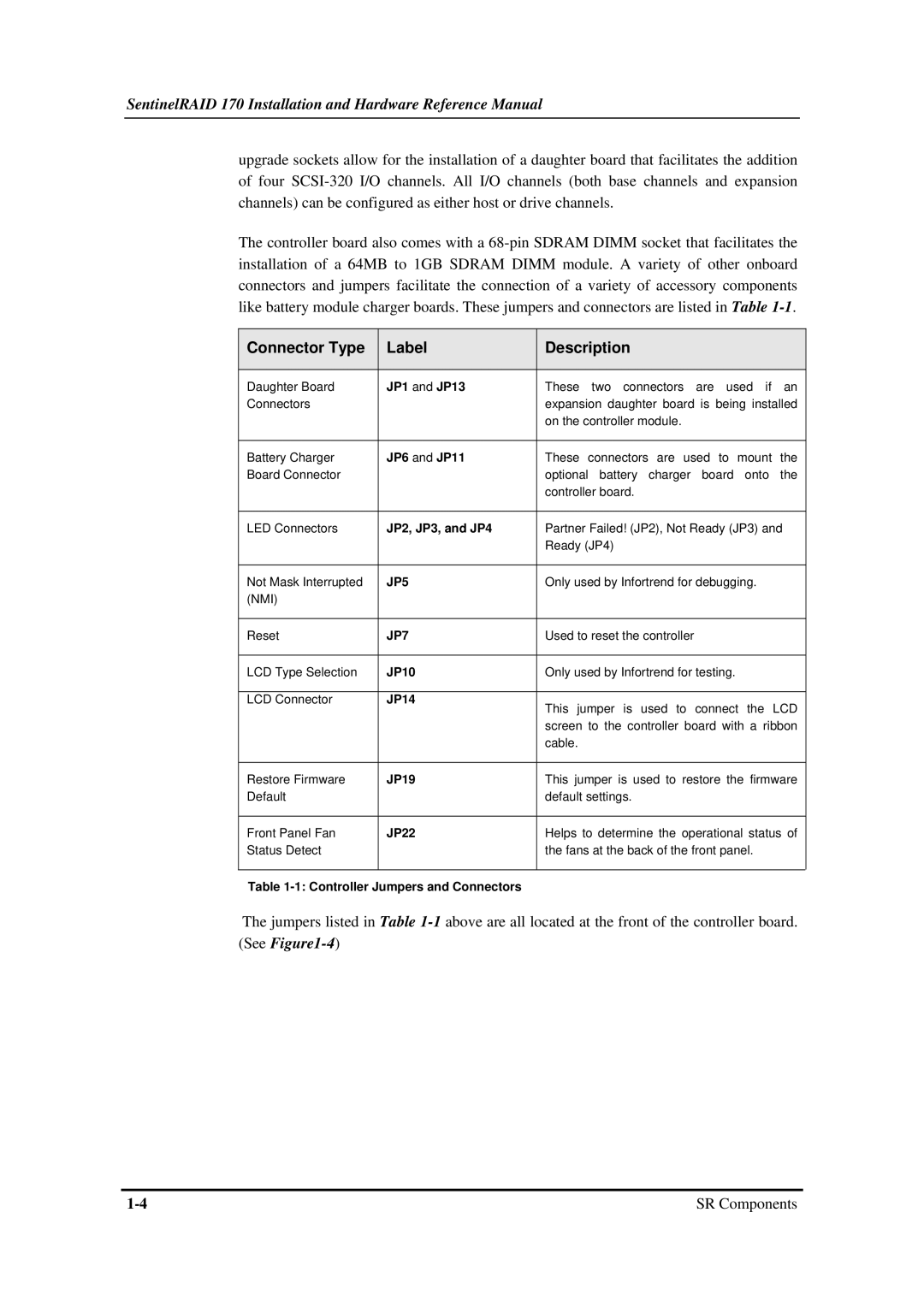
Connector Type | Label | Description |
|
|
|
Daughter Board | JP1 and JP13 | These two connectors are used if an |
Connectors |
| expansion daughter board is being installed |
|
| on the controller module. |
|
|
|
Battery Charger | JP6 and JP11 | These connectors are used to mount the |
Board Connector |
| optional battery charger board onto the |
|
| controller board. |
|
|
|
LED Connectors | JP2, JP3, and JP4 | Partner Failed! (JP2), Not Ready (JP3) and |
|
| Ready (JP4) |
|
|
|
Not Mask Interrupted | JP5 | Only used by Infortrend for debugging. |
(NMI) |
|
|
|
|
|
Reset | JP7 | Used to reset the controller |
|
|
|
LCD Type Selection | JP10 | Only used by Infortrend for testing. |
|
|
|
LCD Connector | JP14 | This jumper is used to connect the LCD |
|
| |
|
| screen to the controller board with a ribbon |
|
| cable. |
|
|
|
Restore Firmware | JP19 | This jumper is used to restore the firmware |
Default |
| default settings. |
|
|
|
Front Panel Fan | JP22 | Helps to determine the operational status of |
Status Detect |
| the fans at the back of the front panel. |
|
|
|
Table
The jumpers listed in Table
SR Components |