Chapter 2: Installation
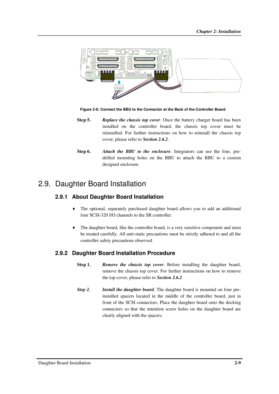
Figure 2-6: Connect the BBU to the Connector at the Back of the Controller Board
Step 5. Replace the chassis top cover. Once the battery charger board has been installed on the controller board, the chassis top cover must be reinstalled. For further instructions on how to reinstall the chassis top cover, please refer to Section 2.6.2.
Step 6. Attach the BBU to the enclosure. Integrators can use the four, pre- drilled mounting holes on the BBU to attach the BBU to a custom designed enclosure.
2.9.Daughter Board Installation
2.9.1About Daughter Board Installation
♦The optional, separately purchased daughter board allows you to add an additional four
♦The daughter board, like the controller board, is a very sensitive component and must be treated carefully. All
2.9.2Daughter Board Installation Procedure
Step 1. Remove the chassis top cover. Before installing the daughter board, remove the chassis top cover. For further instructions on how to remove the top cover, please refer to Section 2.6.2.
Step 2. Install the daughter board. The daughter board is mounted on four pre- installed spacers located in the middle of the controller board, just in front of the SCSI connectors. Place the daughter board onto the docking connectors so that the retention screw holes on the daughter board are clearly aligned with the spacers.
Daughter Board Installation |