Chapter 4: Controller Connections and Operation
|
|
|
|
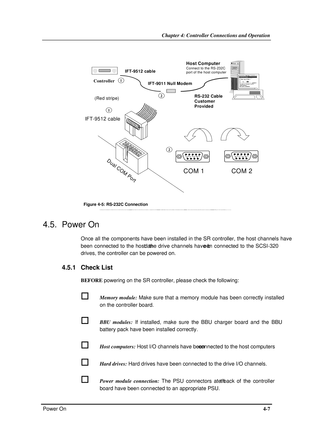
| Host Computer |
|
|
|
| Connect to the | |
|
|
| |||
|
|
|
| port of the host computer | |
Controller | 1 | ||||
|
|
| |||
(Red stripe) |
| 2 |
| ||
|
| ||||
|
| ||||
|
|
| Customer | ||
|
|
|
|
| |
Provided
1
2
1 6 2 7 3 8 49 51 6 2 7 3 8 49 5
COM 1 | COM 2 |
Figure 4-5: RS-232C Connection
Two SCSI ports on the six channel models (ES
4.5. Power On
Once all the components have been installed in the SR controller, the host channels have been connected to the host and the drive channels have been connected to the
4.5.1 Check List
BEFORE powering on the SR controller, please check the following:
Memory module: Make sure that a memory module has been correctly installed on the controller board.
BBU modules: If installed, make sure the BBU charger board and the BBU battery pack have been installed correctly.
Host computers: Host I/O channels have been connected to the host computers
Hard drives: Hard drives have been connected to the drive I/O channels.
Power module connection: The PSU connectors at the back of the controller board have been connected to an appropriate PSU.
Power On |