Chapter 2: Installation
♦During normal use, an empty cell pack takes about 20 hours to recharge.
♦Disconnect the BBU if there is a long storage period before deployment. Extreme storage conditions should be avoided (i.e., temperatures
2.8.2BBU Installation Procedure
Step 1. Remove the chassis top cover. Before installing the BBU module, remove the chassis top cover. For further instructions on how to remove the top cover, please refer to Section 2.6.2.
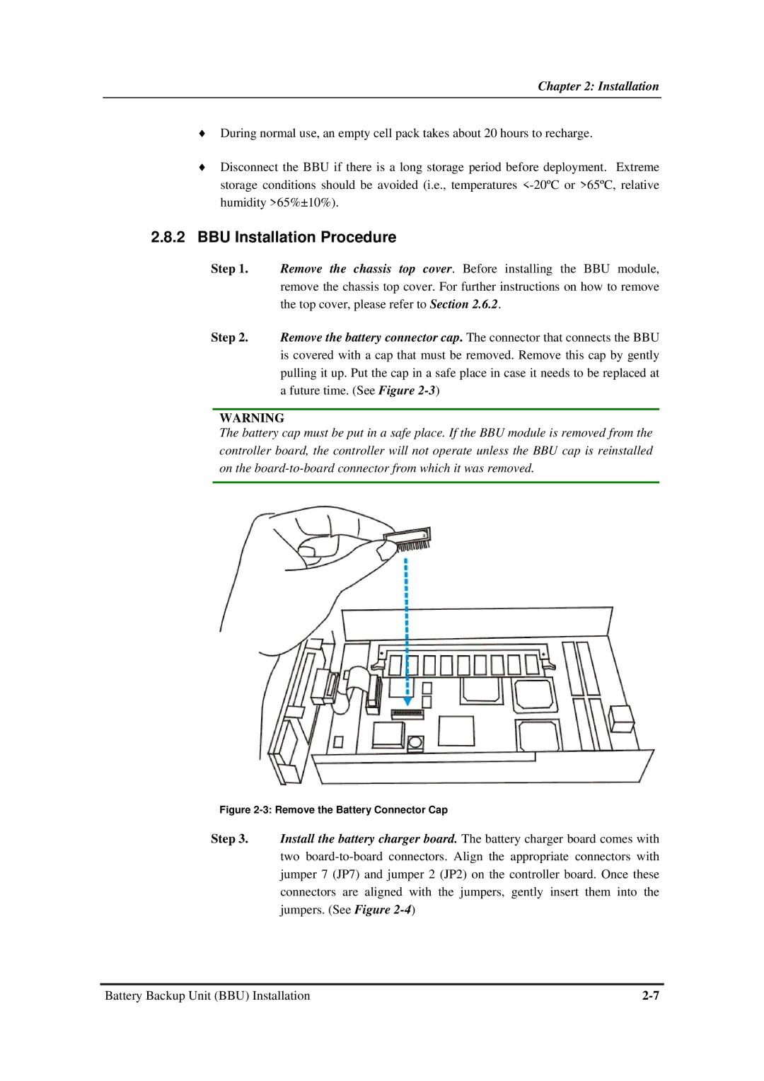
Step 2. Remove the battery connector cap. The connector that connects the BBU is covered with a cap that must be removed. Remove this cap by gently pulling it up. Put the cap in a safe place in case it needs to be replaced at a future time. (See Figure
WARNING
The battery cap must be put in a safe place. If the BBU module is removed from the controller board, the controller will not operate unless the BBU cap is reinstalled on the
Figure 2-3: Remove the Battery Connector Cap
Step 3. Install the battery charger board. The battery charger board comes with two
Battery Backup Unit (BBU) Installation |