11

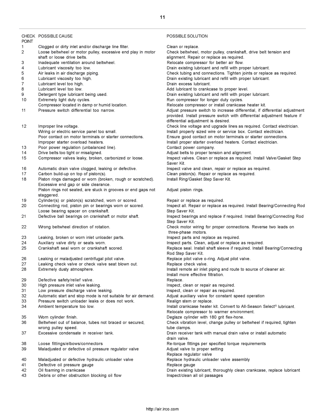
CHECK POSSIBLE CAUSE

POINT

1Clogged or dirty inlet and/or discharge line filter.

2Loose beltwheel or motor pulley, excessive end play in motor shaft or loose drive belts.

3Inadequate ventilation around beltwheel.

4Lubricant viscosity too low.

5Air leaks in air discharge piping.

6Lubricant viscosity too high.

7Lubricant level too high.

8Lubricant level too low.

9Detergent type lubricant being used.

10Extremely light duty cycles.

Compressor located in damp or humid location.

11Pressure switch differential too narrow.

12Improper line voltage.

Wiring or electric service panel too small.

Poor contact on motor terminals or starter connections. Improper starter overload heaters.

13Poor power regulation (unbalanced line).

14Drive belts too tight or misaligned.

15Compressor valves leaky, broken, carbonized or loose.

16Automatic drain valve clogged, leaking or defective.

17Carbon build-up on top of piston(s).

18Piston rings damaged or worn (broken, rough or scratched). Excessive end gap or side clearance.

Piston rings not seated, are stuck in grooves or end gaps not staggered.

19Cylinder(s) or piston(s) scratched, worn or scored.

20Connecting rod, piston pin or bearings worn or scored. Loose bearing spacer on crankshaft.

21Defective ball bearings on crankshaft or motor shaft.

22Wrong beltwheel direction of rotation.

23Leaking, broken or worn inlet unloader parts.

24Auxiliary valve dirty or seats worn.

25Crankshaft seal worn or crankshaft scored.

26Leaking or maladjusted centrifugal pilot valve.

27Leaking check valve or check valve seat blown out.

28Extremely dusty atmosphere.

29Defective safety/relief valve.

30High pressure inlet valve leaking.

31Low pressure discharge valve leaking.

32Automatic start and stop mode is not suitable for air demand.

33Pressure switch unloader leaks or does not work.

34Ambient temperature too low.

35Worn cylinder finish.

36Beltwheel out of balance, tubes not braced or secured, wrong pulley speed.

37Excessive condensate in receiver tank.

38Loose fittings/elbows/connectors

39Maladjusted or defective oil pressure regulator valve

40Maladjusted or defective hydraulic unloader valve

41Defective oil pressure gauge

42Oil foaming in crankcase

43Debris or other obstruction blocking oil flow

POSSIBLE SOLUTION

Clean or replace.

Check beltwheel, motor pulley, crankshaft, drive belt tension and alignment. Repair or replace as required.

Relocate compressor for better air flow.

Drain existing lubricant and refill with proper lubricant.

Check tubing and connections. Tighten joints or replace as required. Drain existing lubricant and refill with proper lubricant.

Drain excess lubricant.

Add lubricant to crankcase to proper level.

Drain existing lubricant and refill with proper lubricant.

Run compressor for longer duty cycles.

Relocate compressor or install crankcase heater kit.

Adjust pressure switch to increase differential, if differential adjustment provided. Install pressure switch with differential adjustment feature if differential adjustment is desired.

Check line voltage and upgrade lines as required. Contact electrician. Install properly sized wire or service box. Contact electrician. Ensure good contact on motor terminals or starter connections. Install proper starter overload heaters. Contact electrician.

Contact power company.

Adjust belts to proper tension and alignment.

Inspect valves. Clean or replace as required. Install Valve/Gasket Step Saver Kit.

Inspect valve and clean, repair or replace as required. Clean piston(s). Repair or replace as required.

Install Ring/Gasket Step Saver Kit.

Adjust piston rings.

Repair or replace as required.

Inspect all. Repair or replace as required. Install Bearing/Connecting Rod Step Saver Kit.

Inspect bearings and replace if required. Install Bearing/Connecting Rod Step Saver Kit.

Check motor wiring for proper connections. Reverse two leads on three-phase motors.

Inspect parts and replace as required.

Inspect parts. Clean, adjust or replace as required.

Replace seal. Install shaft sleeve if required. Install Bearing/Connecting Rod Step Saver Kit.

Replace pilot valve o-ring. Adjust pilot valve. Replace check valve.

Install remote air inlet piping and route to source of cleaner air. Install more effective filtration.

Replace.

Inspect, clean or repair as required. Inspect, clean or repair as required.

Adjust auxiliary valve for constant speed operation Realign stem or replace.

Install crankcase heater kit. Convert to All-Season Select® lubricant. Relocate compressor to warmer environment.

Deglaze cylinder with 180 grit flex-hone.

Check vibration level, change pulley or beltwheel if required, tighten tube clamps.

Drain receiver tank with manual drain valve or install automatic drain valve.

Re-torque fittings per specified torque requirements Adjust valve to proper setting

Replace regulator valve

Replace hydraulic unloader valve assembly

Replace gauge

Drain existing lubricant, thoroughly clean crankcase, replace lubricant Inspect/clean all oil passages

http://air.irco.com

Page 11
Image 11
Ingersoll-Rand 2000P owner manual Check Possible Cause Point, Possible Solution

2000P, 2000 specifications

Ingersoll-Rand is a reputable name in the manufacturing of industrial equipment, and their air compressors, specifically the Ingersoll-Rand 2000 and 2000P models, stand out in their category for exceptional performance and durability. Designed for demanding applications, these compressors have become essential tools for various industries such as construction, manufacturing, and automotive.

One of the main features of the Ingersoll-Rand 2000 and 2000P is their robust construction. These models are built to withstand harsh working environments, with high-quality materials that ensure longevity and reliability. The powerful engine offers impressive air power, delivering consistent airflow to suit various pneumatic tools effectively.

Another notable characteristic is the innovative pump design. The Ingersoll-Rand 2000 series utilizes a two-stage compressor design, allowing for higher efficiency in air compression. This design leads to reduced energy consumption, making these models not only powerful but also cost-effective over long-term use. The advanced engineering also minimizes wear and tear, which significantly extends the service life of the compressor.

Ingersoll-Rand incorporates cutting-edge technology in the 2000 and 2000P models. A standout feature is the integrated control system, which offers users real-time data and monitoring capabilities. This feature helps in maintaining optimal operating conditions and ensuring the compressor runs efficiently, reducing the risk of overheating or overloading.

Moreover, both models come equipped with a noise-reduction technology, which is vital for those looking to minimize noise levels on job sites. This feature makes the Ingersoll-Rand 2000 and 2000P ideal for urban environments or situations where noise restrictions are in place.

Portability is another significant advantage of these compressors. The compact design and inclusion of wheels and handles make it easy to transport the units, allowing users to move them to various work sites with ease.

In summary, the Ingersoll-Rand 2000 and 2000P air compressors are defined by their durability, efficiency, advanced technology, and user-friendly features. Their commitment to providing high-quality performance and reliability makes them an excellent choice for professionals seeking effective solutions for their air compression needs. Whether in a workshop or on a construction site, these compressors offer the necessary power and functionality to get the job done right.