Connecting the remote zone (Zone 2) speakers
(DTR-6.3 only)
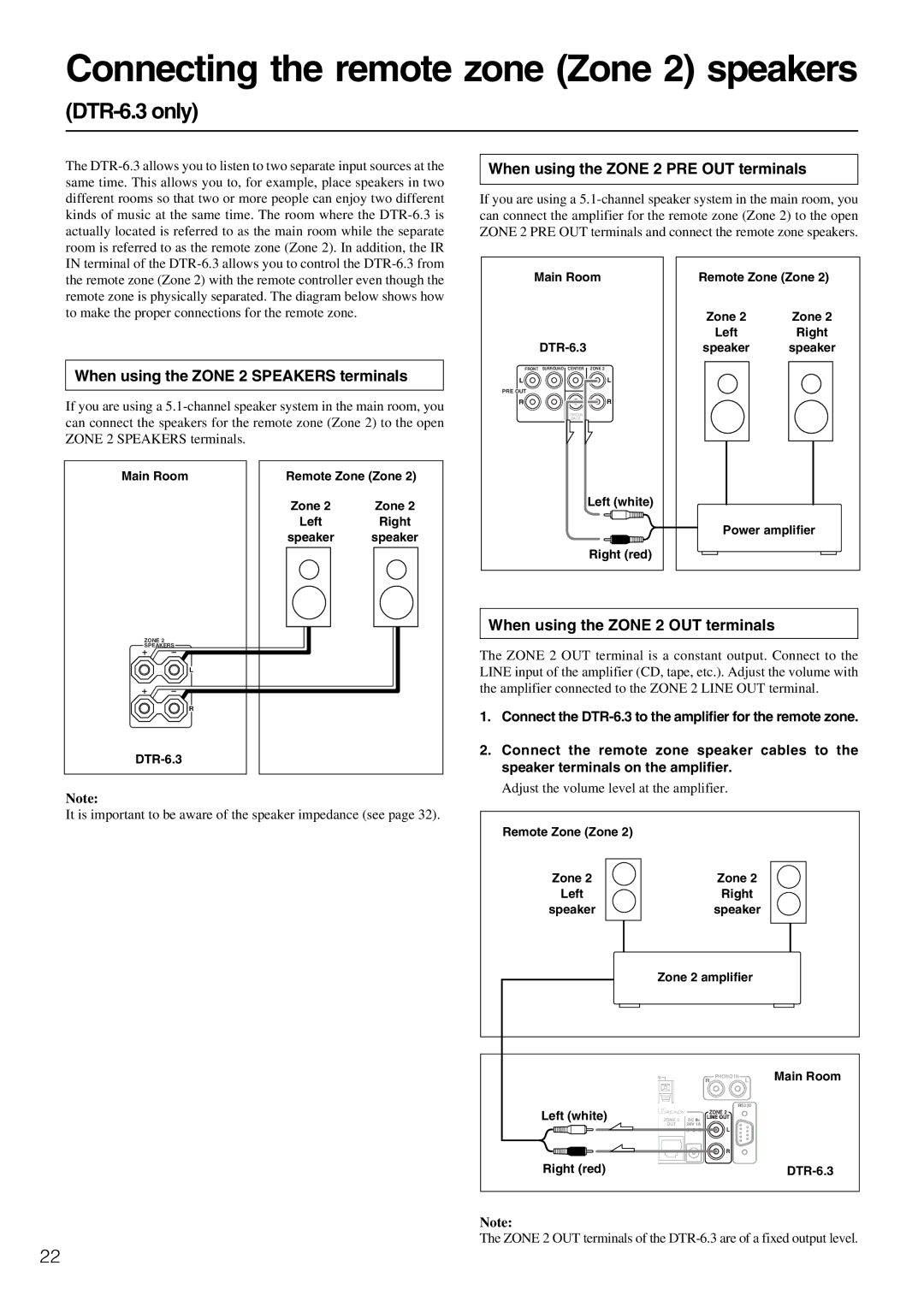
The
When using the ZONE 2 PRE OUT terminals
If you are using a
the remote zone (Zone 2) with the remote controller even though the remote zone is physically separated. The diagram below shows how to make the proper connections for the remote zone.
When using the ZONE 2 SPEAKERS terminals
If you are using a
Main Room | Remote Zone (Zone 2) | |
| Zone 2 | Zone 2 |
| Left | Right |
| speaker | speaker |
Main Room
FRONT SURROUND CENTER ZONE 2
L ![]()
![]()
![]()
![]() L
L
PRE OUT
R ![]()
![]()
![]()
![]() R
R
SURROUND
BACK
Left (white)
Right (red)
Remote Zone (Zone 2)
| Zone 2 |
| Zone 2 | |||
| Left |
| Right | |||
speaker |
| speaker | ||||
|
|
|
|
|
|
|
|
|
|
|
|
|
|
|
|
|
|
|
|
|
Power amplifier
ZONE 2
SPEAKERS
L
R
Note:
It is important to be aware of the speaker impedance (see page 32).
When using the ZONE 2 OUT terminals
The ZONE 2 OUT terminal is a constant output. Connect to the LINE input of the amplifier (CD, tape, etc.). Adjust the volume with the amplifier connected to the ZONE 2 LINE OUT terminal.
1.Connect the
2.Connect the remote zone speaker cables to the speaker terminals on the amplifier.
Adjust the volume level at the amplifier.
Remote Zone (Zone 2)
Zone 2 | Zone 2 |
Left | Right |
speaker | speaker |
| Zone 2 amplifier |
| |||
| M |
| R | PHONO IN | Main Room |
|
|
| L | ||
|
|
|
| RS232 |
|
Left (white) |
|
|
| ZONE 2 |
|
ZONE 2 | DC IN | LINE OUT |
| ||
| OUT | 24V 1A |
| L |
|
|
|
|
|
| |
|
|
|
| R |
|
Right (red) |
|
|
|
| |
Note:
The ZONE 2 OUT terminals of the
22
