Operating components not reached by the remote controller signals (IR IN)
In order to use the remote controller to control the
•Onkyo’s
•Multiroom A/V distribution and control system such as those from Niles® and Xantech®
If the remote controller signal does not reach the
If the
DTR-6.3 only:
With this connection, select “Main” at “Preference” → “IR IN Position” (see page 56).
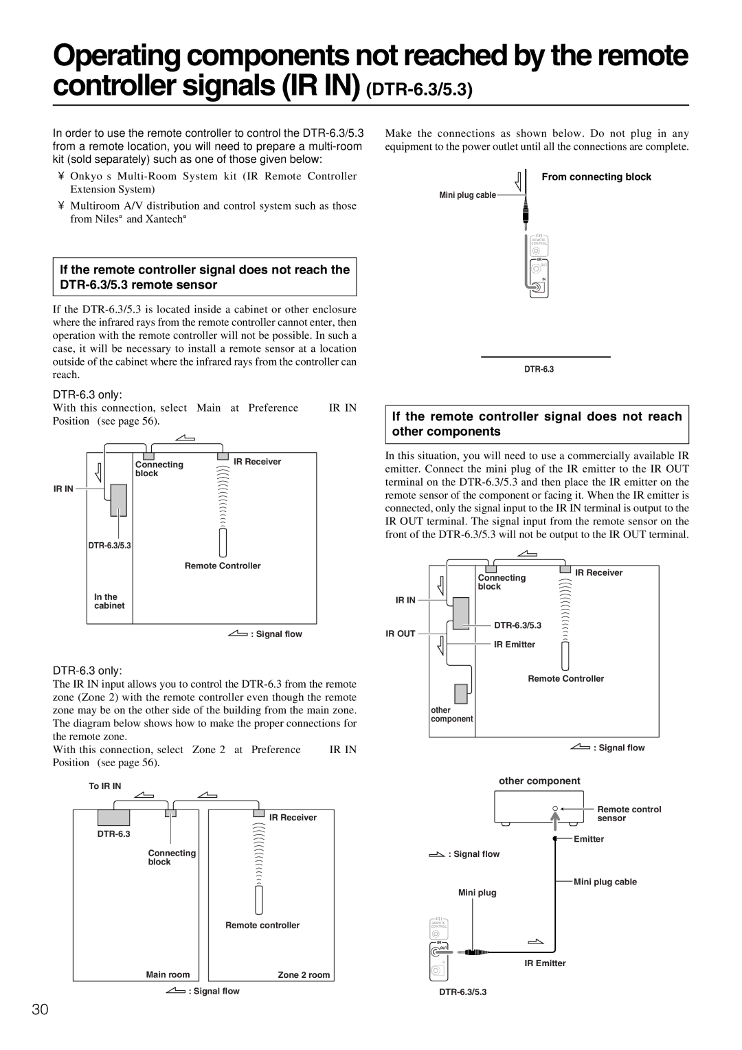
Make the connections as shown below. Do not plug in any equipment to the power outlet until all the connections are complete.
From connecting block
Mini plug cable ![]()
REMOTE
CONTROL
IR
OUT
IN
If the remote controller signal does not reach other components
IR IN
Connecting | IR Receiver |
block |
|
Remote Controller
In this situation, you will need to use a commercially available IR emitter. Connect the mini plug of the IR emitter to the IR OUT terminal on the
In the cabinet
Connecting block
IR IN
IR Receiver
![]()
![]() : Signal flow
: Signal flow
The IR IN input allows you to control the
With this connection, select “Zone 2” at “Preference” → “IR IN Position” (see page 56).
To IR IN
IR Receiver
Connecting block
Remote controller
Main room | Zone 2 room |
![]() : Signal flow
: Signal flow
IR OUT
IR Emitter
Remote Controller
other component
![]() : Signal flow
: Signal flow
other component
![]()
![]() Remote control sensor
Remote control sensor
![]() Emitter
Emitter
![]() : Signal flow
: Signal flow
Mini plug cable
Mini plug
REMOTE
CONTROL
IR
OUT
IN | IR Emitter |
|
30