Connections (DTR-5.3)
 : Signal flow
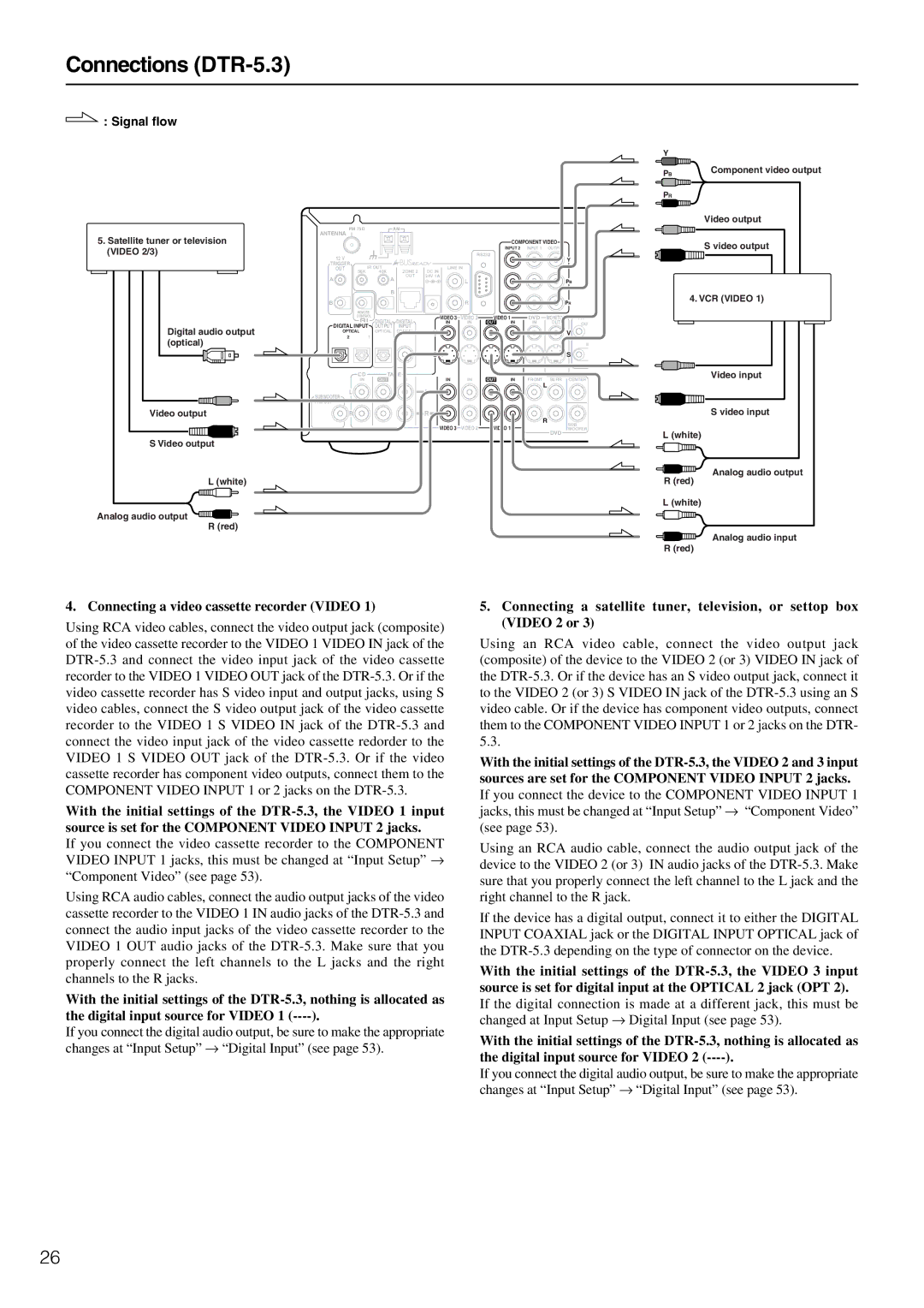
Y
PB | Component video output |
PR |
|
|
|
|
|
|
|
|
|
|
|
|
| Video output |
| ANTENNA | FM 75 |
| AM |
|
|
|
|
|
|
| |
5. Satellite tuner or television |
|
|
|
|
|
|
|
|
|
|
| |
|
|
|
|
|
|
|
| COMPONENT VIDEO | S video output | |||
(VIDEO 2/3) |
|
|
|
|
|
|
| INPUT 2 | INPUT 1 | OUTPUT | ||
12 V |
|
|
|
|
| RS232 |
|
|
| Y | ||
|
|
|
|
|
|
|
|
|
|
| ||
| TRIGGER | IR OUT |
| LINE IN |
|
|
|
|
| |||
| OUT | 56K | ZONE 2 |
|
|
|
|
| ||||
|
|
| 40K | DC IN |
|
|
|
|
|
| ||
| A |
|
| A | OUT | 24V 1A | L |
|
|
|
| PB |
|
|
|
|
|
|
|
|
| ||||
|
|
|
| B |
|
|
|
|
|
|
| 4. VCR (VIDEO 1) |
| B |
|
|
|
|
| R |
|
|
|
| |
|
|
|
|
|
|
|
|
| PR | |||
|
| REMOTE |
|
|
|
|
|
|
|
|
| |
|
| CONTROL | DIGITAL |
| VIDEO 3 | VIDEO 2 | VIDEO 1 |
| DVD | MONITOR | IR | |
|
|
|
| DIGITAL |
| |||||||
| DIGITAL INPUT | IN | IN | OUT | IN | IN | OUT | OUT | ||||
Digital audio output | OUTPUT | INPUT | V |
|
|
|
|
| V | |||
OPTICAL |
| OPTICAL | COAXIAL |
|
|
|
|
| ||||
(optical) |
| 2 | 1 |
|
|
|
|
|
|
|
|
|
|
|
|
|
|
|
|
|
|
|
| IN | |
|
|
|
|
|
| S |
|
|
|
|
| S |
|
| CD |
| TAPE | IN | IN | OUT | IN | FRONT | SURR | Video input | |
|
| IN |
| OUT | IN | CENTER | ||||||
|
| L |
|
|
| L |
|
|
|
| L |
|
| SUBWOOFER |
|
|
|
|
|
|
|
|
| ||
|
|
|
|
|
|
|
|
|
|
|
| |
| PRE OUT |
|
|
|
|
|
|
|
|
|
|
|
Video output |
| R |
|
|
| R |
|
|
|
| R | S video input |
|
|
|
|
|
|
|
|
|
|
| SUB | |
|
|
|
|
|
| VIDEO 3 | VIDEO 2 | VIDEO 1 |
|
| DVD | WOOFER |
|
|
|
|
|
|
|
|
|
|
| L (white) | |
S Video output |
|
|
|
|
|
|
|
|
|
|
| |
|
|
|
|
|
|
|
|
|
|
|
| |
Analog audio output
L (white) | R (red) |
L (white)
Analog audio output ![]() R (red)
R (red)
![]() Analog audio input R (red)
Analog audio input R (red)
4. Connecting a video cassette recorder (VIDEO 1)
Using RCA video cables, connect the video output jack (composite) of the video cassette recorder to the VIDEO 1 VIDEO IN jack of the
With the initial settings of the
If you connect the video cassette recorder to the COMPONENT VIDEO INPUT 1 jacks, this must be changed at “Input Setup” → “Component Video” (see page 53).
Using RCA audio cables, connect the audio output jacks of the video cassette recorder to the VIDEO 1 IN audio jacks of the
With the initial settings of the
If you connect the digital audio output, be sure to make the appropriate changes at “Input Setup” → “Digital Input” (see page 53).
5.Connecting a satellite tuner, television, or settop box (VIDEO 2 or 3)
Using an RCA video cable, connect the video output jack (composite) of the device to the VIDEO 2 (or 3) VIDEO IN jack of the
With the initial settings of the
Using an RCA audio cable, connect the audio output jack of the device to the VIDEO 2 (or 3) IN audio jacks of the
If the device has a digital output, connect it to either the DIGITAL INPUT COAXIAL jack or the DIGITAL INPUT OPTICAL jack of the
With the initial settings of the
If the digital connection is made at a different jack, this must be changed at Input Setup → Digital Input (see page 53).
With the initial settings of the
If you connect the digital audio output, be sure to make the appropriate changes at “Input Setup” → “Digital Input” (see page 53).
26