Connections (DTR-5.3)
 : Signal flow
|
|
|
|
|
|
|
|
|
|
| 6. TV monitor or projector |
|
|
|
|
|
|
|
|
|
|
| (MONITOR OUT) |
ANTENNA | FM 75 |
|
| AM |
|
|
|
|
|
|
|
|
|
|
|
|
|
|
|
|
|
| |
|
|
|
|
|
|
|
| COMPONENT VIDEO |
| ||
|
|
|
|
|
|
|
| INPUT 2 | INPUT 1 | OUTPUT | Y |
12 V |
|
|
|
|
| RS232 |
|
| Y | ||
|
|
|
|
|
|
|
|
|
| ||
TRIGGER | IR OUT |
| LINE IN |
|
|
|
|
| |||
OUT | 56K | ZONE 2 |
|
|
|
|
| ||||
|
| 40K | DC IN |
|
|
|
|
| PB | ||
A |
|
|
| OUT | 24V 1A |
|
|
|
|
| |
|
| A |
| L |
|
|
| PB | |||
|
|
| B |
|
|
|
|
|
| Component video input | |
B |
|
|
|
|
| R |
|
|
| PR | |
|
|
|
|
|
|
|
| PR | |||
| REMOTE |
|
|
|
|
|
|
|
|
| |
| CONTROL | DIGITAL |
| VIDEO 3 | VIDEO 2 | VIDEO 1 | DVD | MONITOR | IR | ||
DIGITAL INPUT | DIGITAL | IN | IN | OUT | IN | IN | OUT | OUT | |||
OUTPUT | INPUT |
|
|
|
|
|
|
| |||
OPTICAL |
| OPTICAL | COAXIAL | V |
|
|
|
| V |
| |
| 2 | 1 |
|
|
|
|
|
|
| ||
|
|
|
|
|
|
|
|
|
| ||
|
|
|
|
|
|
|
|
|
|
| IN |
|
|
|
|
| S |
|
|
|
| S | Video input |
CD |
| TAPE | IN | IN | IN |
| OUT | ||||
IN | |||||
L ![]()
![]()
![]()
![]() L
L
SUBWOOFER
PRE OUT
R ![]()
![]()
![]()
![]() R
R
VIDEO 3 VIDEO 2
OUT IN FRONT SURR | CENTER | |
L | S Video input | |
R | SUB | |
VIDEO 1 | ||
WOOFER |
DVD
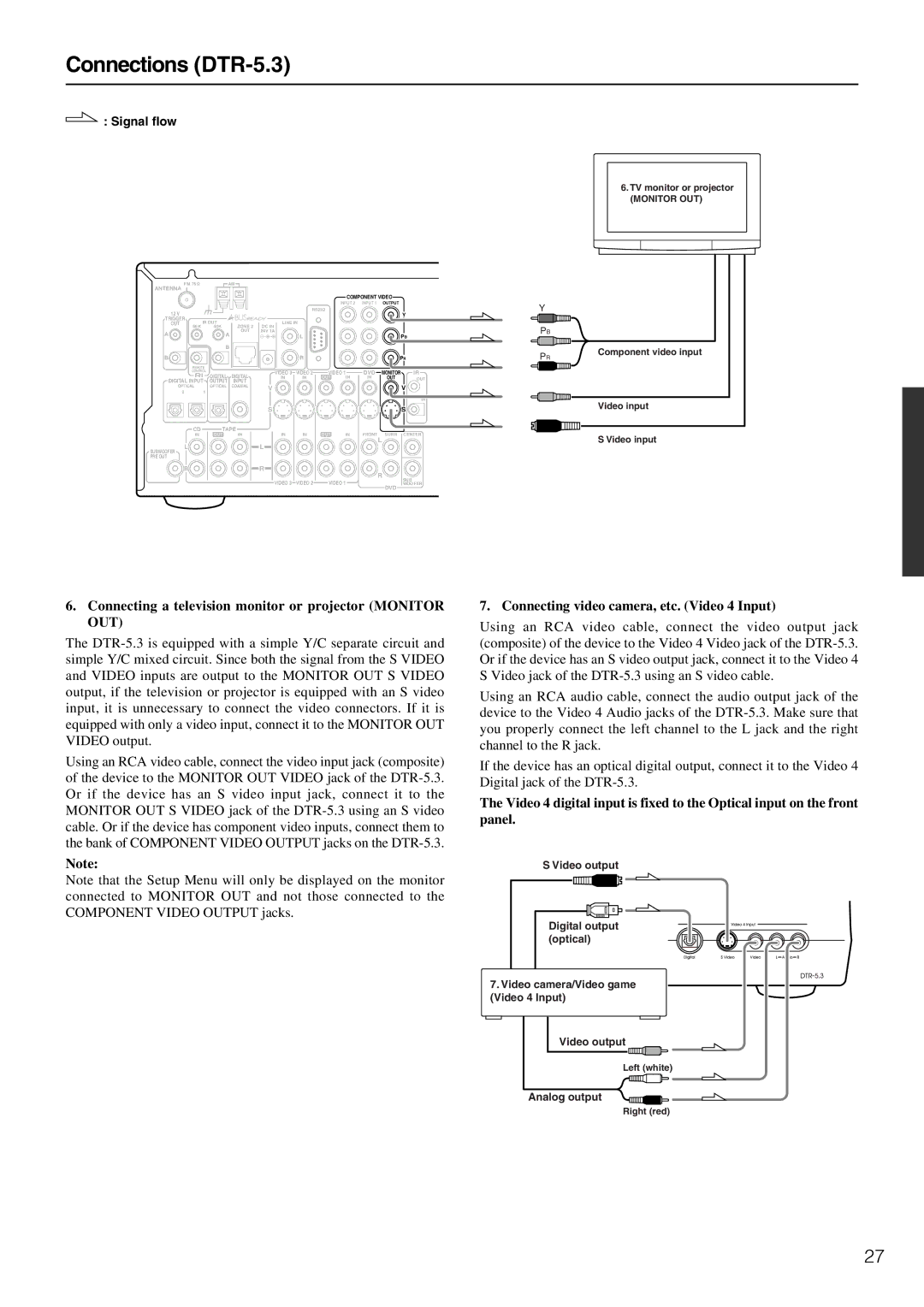
6.Connecting a television monitor or projector (MONITOR OUT)
The
Using an RCA video cable, connect the video input jack (composite) of the device to the MONITOR OUT VIDEO jack of the
Note:
Note that the Setup Menu will only be displayed on the monitor connected to MONITOR OUT and not those connected to the COMPONENT VIDEO OUTPUT jacks.
7. Connecting video camera, etc. (Video 4 Input)
Using an RCA video cable, connect the video output jack (composite) of the device to the Video 4 Video jack of the
Using an RCA audio cable, connect the audio output jack of the device to the Video 4 Audio jacks of the
If the device has an optical digital output, connect it to the Video 4 Digital jack of the
The Video 4 digital input is fixed to the Optical input on the front panel.
S Video output
Digital output |
(optical) |
7. Video camera/Video game |
(Video 4 Input) |
Video output
Left (white)
Analog output
Right (red)
27
