82540EP — Networking Silicon
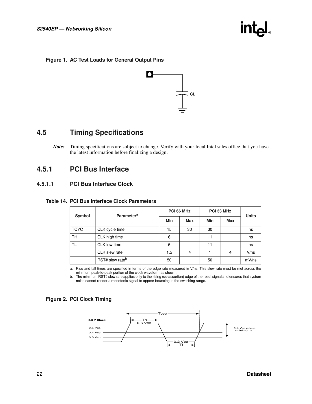
Figure 1. AC Test Loads for General Output Pins
CL
4.5Timing Specifications
Note: Timing specifications are subject to change. Verify with your local Intel sales office that you have the latest information before finalizing a design.
4.5.1PCI Bus Interface
4.5.1.1PCI Bus Interface Clock
Table 14. PCI Bus Interface Clock Parameters
Symbol | Parametera | PCI 66 MHz | PCI 33 MHz | Units | |||
|
|
|
| ||||
Min | Max | Min | Max | ||||
|
|
| |||||
|
|
|
|
|
|
| |
TCYC | CLK cycle time | 15 | 30 | 30 |
| ns | |
|
|
|
|
|
|
| |
TH | CLK high time | 6 |
| 11 |
| ns | |
|
|
|
|
|
|
| |
TL | CLK low time | 6 |
| 11 |
| ns | |
|
|
|
|
|
|
| |
| CLK slew rate | 1.5 | 4 | 1 | 4 | V/ns | |
|
|
|
|
|
|
| |
| RST# slew rateb | 50 |
| 50 |
| mV/ns | |
a.Rise and fall times are specified in terms of the edge rate measured in V/ns. This slew rate must be met across the minimum
b.The minimum RST# slew rate applies only to the rising
Figure 2. PCI Clock Timing
Tcyc
3.3 V Clock |
| Th |
|
0.6 Vcc
0.5Vcc
0.4Vcc
0.3Vcc
0.2 Vcc
Tl
0.4Vcc
22 | Datasheet |