82540EP — Networking Silicon
4.5.2Link Interface Timing
Table 17. Rise and Fall Times
Symbol | Parameter | Condition | Min | Max | Unit |
|
|
|
|
|
|
TR | Clock rise time | 0.8 V to 2.0 V | 0.7 |
| ns |
|
|
|
|
|
|
TF | Clock fall time | 2.0 V to 0.8 V | 0.7 |
| ns |
|
|
|
|
|
|
TR | Data rise time | 0.8 to 2.0 V | 0.7 |
| ns |
|
|
|
|
|
|
TF | Data fall time | 2.0 V to 0.8 V | 0.7 |
| ns |
|
|
|
|
|
|
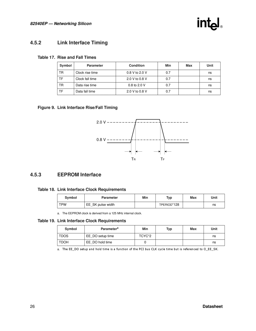
Figure 9. Link Interface Rise/Fall Timing
2.0V
0.8V
TRTF
4.5.3EEPROM Interface
Table 18. Link Interface Clock Requirements
Symbol | Parameter | Min | Typ | Max | Unit |
|
|
|
|
|
|
TPW | EE_SK pulse width |
| TPERIOD*128 |
| ns |
|
|
|
|
|
|
a. The EEPROM clock is derived from a 125 MHz internal clock.
Table 19. Link Interface Clock Requirements
Symbol | Parametera | Min | Typ | Max | Unit |
|
|
|
|
|
|
TDOS | EE_DO setup time | TCYC*2 |
|
| ns |
|
|
|
|
|
|
TDOH | EE_DO hold time | 0 |
|
| ns |
|
|
|
|
|
|
a.
26TheEE_DOsetupandholdtimeisafunctionofthePCIbusCLKcycletimebutisreferencedtoDatasheetO_EE_SK.