Table 40. I/O Map (continued)
Address (hex) | Description |
|
|
8 bytes on an | Unknown |
|
|
96 contiguous bytes starting on a | ICH2 (ACPI + TCO) |
| |
divisible boundary |
|
|
|
64 contiguous bytes starting on a | |
| |
|
|
32 contiguous bytes starting on a | ICH2 (USB controller 1) |
| |
|
|
16 contiguous bytes starting on a | ICH2 (SMBus) |
| |
|
|
4096 contiguous bytes starting on a | Intel 82801BA PCI bridge |
| |
|
|
96 contiguous bytes starting on a | LPC47M102 |
| |
divisible boundary |
|
|
|
Notes:
1.Default, but can be changed to another address range
2.Dword access only
3.Byte access only
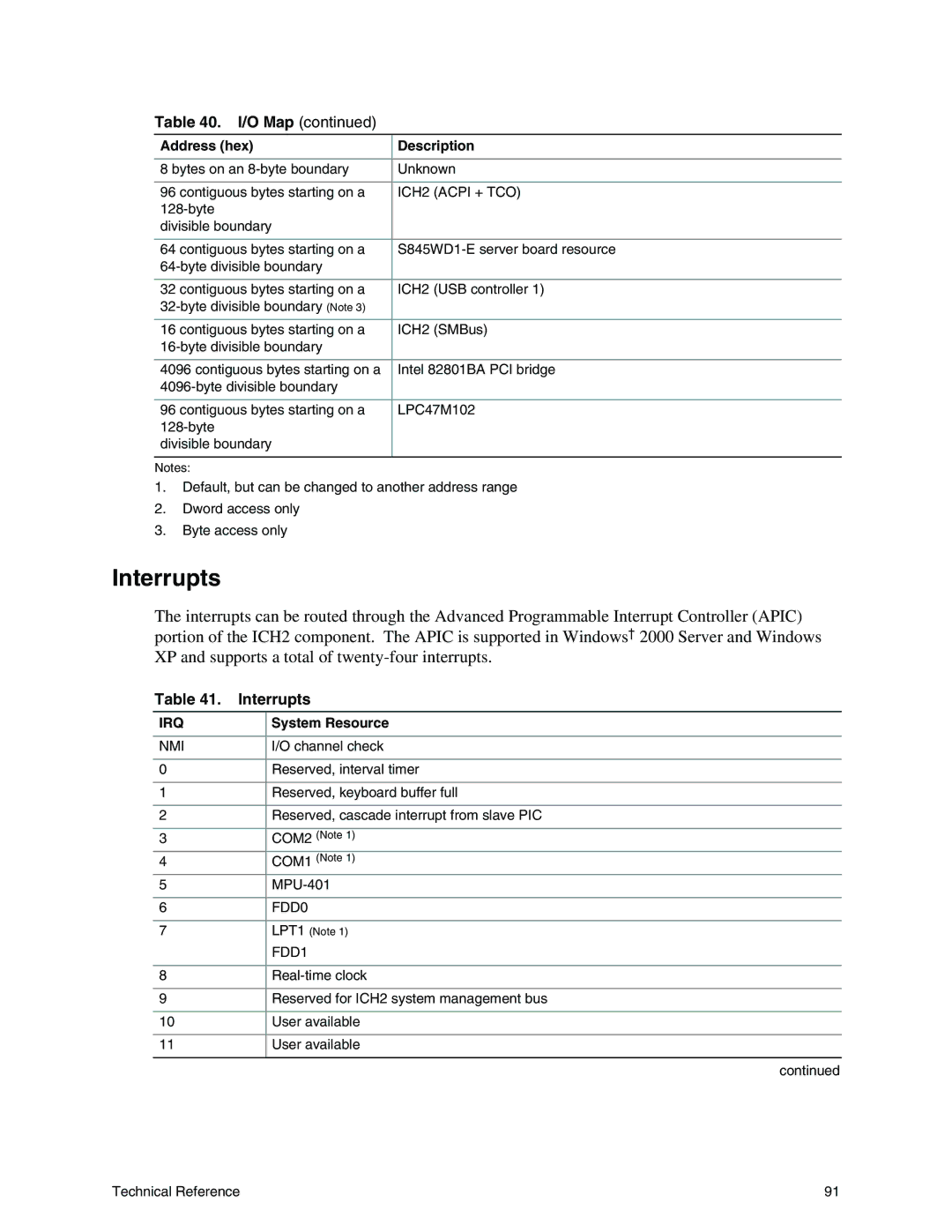
Interrupts
The interrupts can be routed through the Advanced Programmable Interrupt Controller (APIC) portion of the ICH2 component. The APIC is supported in Windows† 2000 Server and Windows XP and supports a total of
Table 41. | Interrupts |
IRQ | System Resource |
|
|
NMI | I/O channel check |
|
|
0 | Reserved, interval timer |
|
|
1 | Reserved, keyboard buffer full |
|
|
2 | Reserved, cascade interrupt from slave PIC |
|
|
3 | COM2 (Note 1) |
4 | COM1 (Note 1) |
5 | |
|
|
6 | FDD0 |
|
|
7 | LPT1 (Note 1) |
| FDD1 |
|
|
8 | |
|
|
9 | Reserved for ICH2 system management bus |
10User available
11User available
continued
Technical Reference | 91 |