Page 23
Installation
•Mount the camera on a large heat sink (camera bracket) made out of
•Make sure the flow of heat from the camera case to the bracket is not blocked by a
•Make sure the camera has enough open space around it to facilitate the free flow of air.
Please contact JAI at (800)
5.2.2Connector Pin Configurations
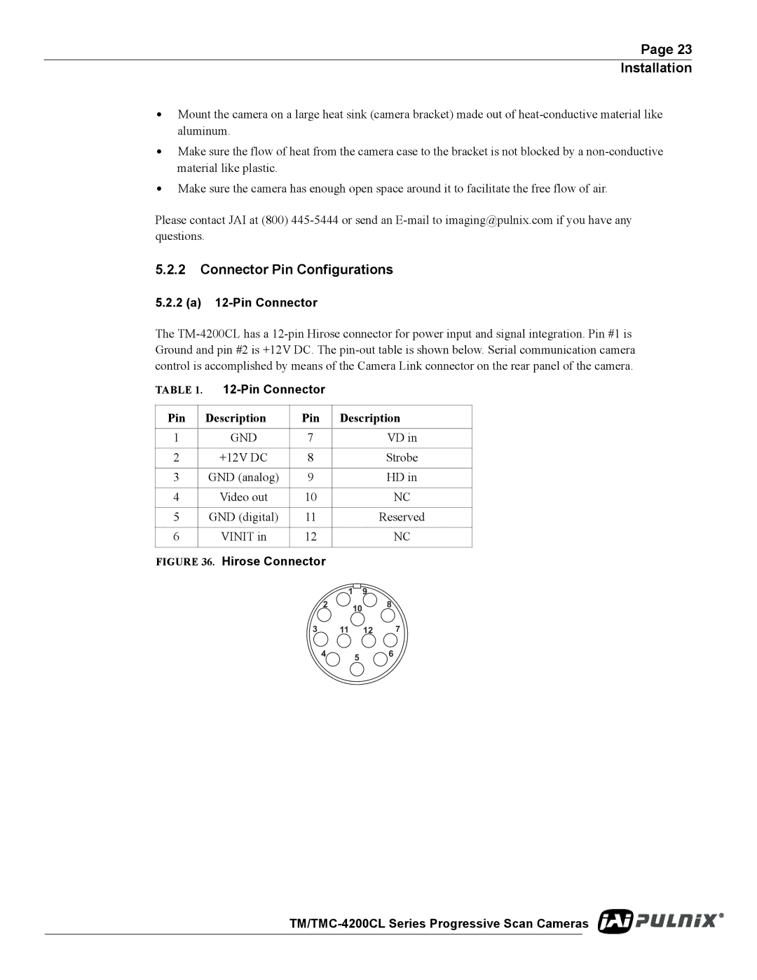
5.2.2 (a) 12-Pin Connector
The
TABLE 1. 12-Pin Connector
Pin | Description | Pin | Description |
|
|
|
|
1 | GND | 7 | VD in |
|
|
|
|
2 | +12V DC | 8 | Strobe |
|
|
|
|
3 | GND (analog) | 9 | HD in |
|
|
|
|
4 | Video out | 10 | NC |
|
|
|
|
5 | GND (digital) | 11 | Reserved |
|
|
|
|
6 | VINIT in | 12 | NC |
|
|
|
|
FIGURE 36. Hirose Connector
1 9
28
10
3 | 11 | 12 | 7 |
4 5 6