Page 44
Functions and Operations
TABLE 6. | Asynchronous Mode Chart |
| ||
|
|
|
|
|
|
| Async no Shutter | Async Preset and Prog. Shutter | PWC |
|
|
|
|
|
|
|
|
|
|
aA |
| <1 line | <1 line | 6 clk |
|
|
|
|
|
aB |
| 9.5 line | (n + 1) lines + 1024 clk | Pulse width + 1024 clk |
|
|
|
|
|
aC |
|
|
| 1024 clk |
|
|
|
|
|
| PIV Fixed Expo | PIV PWC | Unit | |
|
|
|
| |
|
|
|
| |
pA | 6 | 6 |
| |
|
|
|
| |
pB | 200 | 200 |
| |
|
|
|
| |
pC | 160 | 160 | Pixel | |
|
|
| ||
pD | 320 | 320 | ||
| ||||
|
|
|
| |
pE | 20 | 20 |
| |
|
|
|
| |
pF | 1 | 1 | Frame | |
|
|
|
|
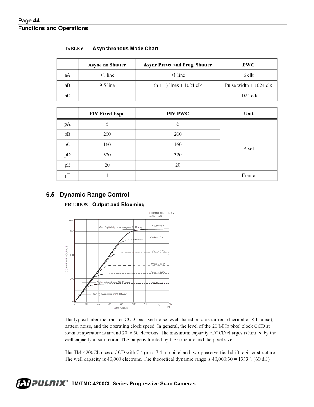
6.5 Dynamic Range Control
FIGURE 59. Output and Blooming
Blooming adj. = 13. 5 V
Lens: F=5.6
mV
Max. Digital dynamic range at 3 dB amp
600
Vsub = 8 V
CCD OUTPUT VOLTAGE
Vsub = 10 V
Vsub = 12 V
400
Vsub = 14 V
Vsub = 16 V
200
|
|
|
|
| Digital saturation at 16 dB amp |
|
| Vsub = 18 V |
|
| ||
|
|
|
|
|
|
|
|
| ||||
|
|
|
|
|
|
|
|
|
|
| ||
0 |
|
|
| Analog saturation at 20 dB amp |
|
|
|
|
| |||
|
|
|
|
|
|
|
| |||||
|
|
|
|
|
|
|
|
|
|
|
| |
0 |
| 20 | 40 | 60 | 80 | 100 | 120 | 140 | 160 | |||
|
|
|
|
|
|
| LUMINANCE |
|
|
| FL | |
|
|
|
|
|
|
|
|
|
|
|
| |
The typical interline transfer CCD has fixed noise levels based on dark current (thermal or KT noise), pattern noise, and the operating clock speed. In general, the level of the 20 MHz pixel clock CCD at room temperature is around 20 to 50 electrons. The maximum capacity of CCD charges is limited by the well capacity at saturation. The range is limited by the structure and the pixel size.
The