Model No. GR-DV1U/AA-V70U
For Customer Use
It is recommended that you
Dear Customer
Benefits Of Lithium-Ion Batteries
About Batteries
Power Lines
Power Sources
Power Cord Protection
Ventilation
Cleaning
Accessories
Damage Requiring Service
Replacement Parts
About DVC
Quick Operation Guide
Install a Fully Charged Battery
Rovided a CCE Ssories
Contents
Etting Started
Charging The Battery
Open Battery Cover
Installing The Battery Pack
Insert Battery
Close Battery Cover
Supply Power
Using The CAM Stand
Etting STA R TED
Indoor Use
Remove OLD Battery
Clock Lithium Battery CR2025 Insertion/Removal
Insert NEW Battery
Open Battery Cover Slide off as shown in the illustration
Select Operation Mode
Date/Time Settings
Access Recording Menu
Input Date and Time
Loading/Unloading a Cassette
Slide the black switch on the back of the tape
Open Cassette Door
INSERT/REMOVE Tape
Adjust Diopter
Diopter Adjustment
Hand Strap Attachment
Attach Hand Strap
Installing The Battery
RM-V708U Remote Control Unit
Insert Battery in Holder
RE-INSERT Holder
Position Auto
Full Auto Manual Mode
Full Auto/Manual Operation
Menus
Set the Power Dial to REC and set the Select Dial to Manual
Select Function
Close Recording Menu
Recor Ding
Wide Mode
DIS Digital Image Stabilizer
Zoom Magnification
Close System Menu
Access System Menu
System Menu
Sound
Scene 5-Second Mode
Beep
Wind Cut
Basic Recording
Turn on Power
Start Recording
END Recording
Re Shoot a Scene
Tape Remaining Indicator
Stable Shooting Positions
Fasten hand strap around wrist For low
Snapshot Search
Snapshot
Zoom in T Tight Zoom OUT W Wide
Zoom
Digital zoom zone 10X zoom zone
To Take a Snapshot In The 5-Second Mode
Select Mode
Dissolve in the 5-Second mode
Scene
To Take a Snapshot In The Self-Timer Mode
Self-Timer
, press Snapshot instead
After 15 sec
Recording From The Middle Of a Tape
Engage Still Mode
Start Search
Recording START/STOP
Displaying The Date And Time During Recording
Select Effect
FADE/WIPE Effects
On Next
After 2 sec
Fades and Wipes
Resume Recording
Picture Wipe/Dissolve
Dissolve
Press Recording START/STOP
Press Recording START/STOP, and ? P
Random Variations
? R Random Fader
Exchanging FADE/WIPE Effects
Accessmenu FADER/WIPE Customize
Select NEW Effect
Close Menu
AE/Effects
Accessmenu Production Effects
Video Echo Sepia √
Monotone √
Classic Film √
Twilight √
Set the Select Dial to PRO
Access Production Effects Customize Menu
Exchanging P.AE/Effects
To Change To Auto Focus
Manual Focus Adjustment
Adjust Focus
To Return To Automatic Exposure Control
Adjust Exposure
Exposure Control
Iris Lock
Enter Selection
White Balance Adjustment
To Return To Automatic White Balance
Select Auto in . Or set the Select Dial to
MWB Operation
Enter Setting
SET MWB
To Change The Tint For Recording
Charging The GR-DV1 Battery
Using The Remote Control During Playback
Playba CK Basic Connections
Docking Station Attachment
TV Playback
Select TV’S Video Mode
Connect Docking Station to TV or VCR
Connectinput VCR Output to TV Start Playback
Connectvcr Camcorder to TV or
Turn on the power to the camcorder and the TV/VCR
Attach CAM Stand to Camcorder
Connect as shown in the illustration
Open Cover
Still Playback
Watch Recording
To Perform High-Speed Search
PL Ayback
Access Playback Menu
Playback Menu
To set parameters for other functions, repeat steps 2
Displaying The Time Code During Playback
Playback Sound
Displaying the Date During Playback
Recording Sound Display Output Sound
Playback Zoom
Playback Advanced Features
Playback Program AE/Effects
Dubbing
Docking Station
Make Connections
VCR Recording deck
Enter Brand
Brand Setting
Release SET Button
Operation Confirmation
Random Assemble Editing
EDI Ting
Start Source Playback
Execute FADE/WIPE
SET EDIT-OUT Point
SET EDIT-IN Point
USE Fade Wipe on Scene Transition
USE P.AE/EFFECT
Start Editing
Engagemode Vcrs RECORD-PAUSE
Stop Editing
Engage the Stop modes for the camcorder and the recorder
Prepare for R.A. Edit Play Back Dubbed Scene
For More Accurate Editing
Choose a Scene
RM-V708U
Press MENU. The Playback Menu appears on the TV screen
Set the Power Dial to Play and press Play
Input Correction Data
Audio Dubbing
Find Edit in Point
Insert Editing
Pause During Editing
Pause
Troubleshooting
Digital Zoom doesn’t
Power Dial
Turn off the Video Echo
Work
Time
Gain UP to AGC or
Are selected at the same
Audio/Video Cable And CAM Stand
Cleaning The Camcorder
AFT E R USE
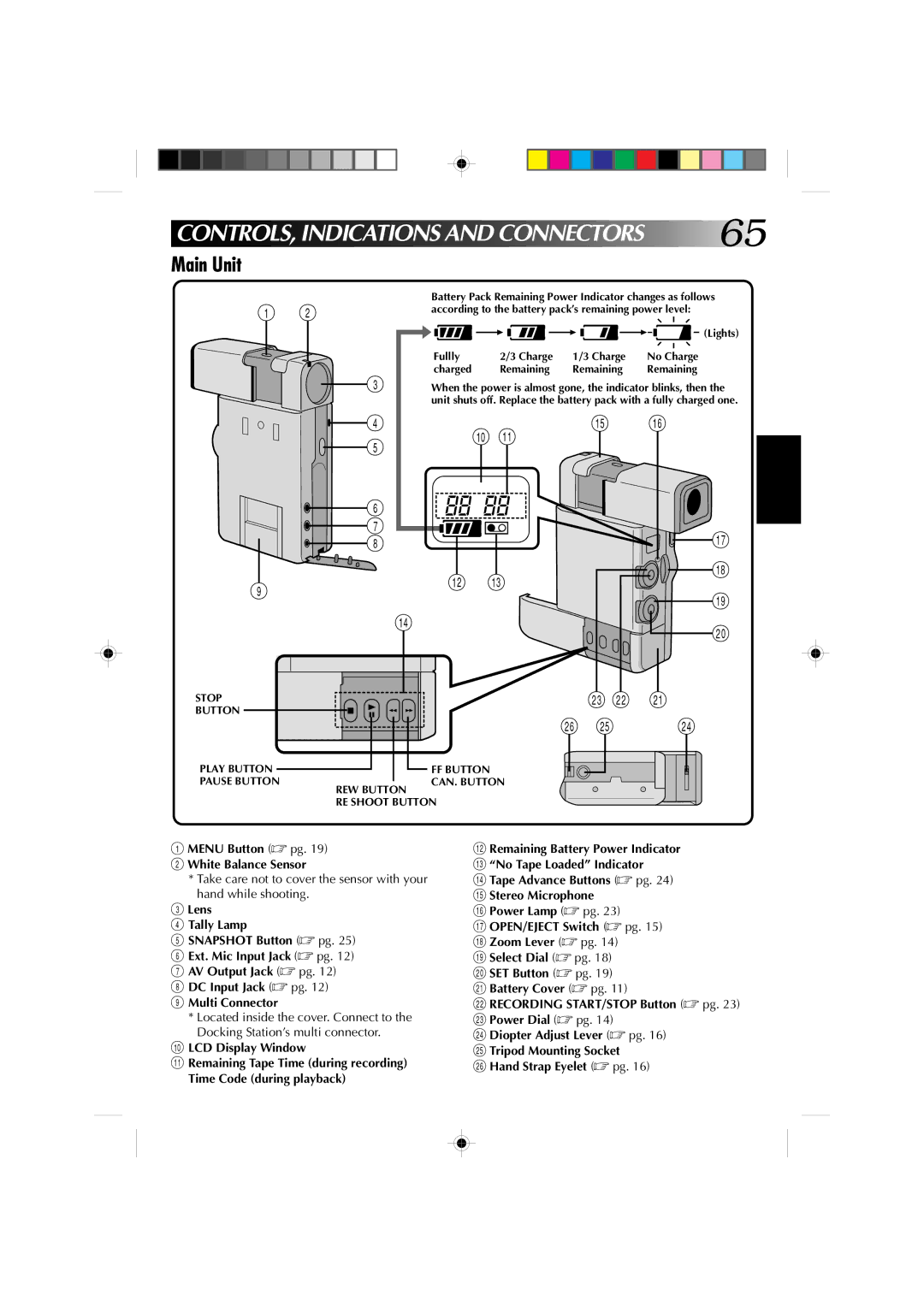
Main Unit
CONTROLS, Indications and Connectors
Menu Button pg White Balance Sensor
LCD Display Window
Name & Function
ROLS, Indications and Connec Tors
Viewfinder Indications
Pause Button
Fan
Fast-Forward FF Button
DC Output Jack
Using Household AC Plug Adapter
To prevent damage and prolong service life
To avoid hazard
To prevent damage to the camcorder
Avoid using the unit
For safety, do not
Dirty heads can cause the folowing Problems
During use
Audio
Connectors
General
Remote Control Unit RM-V708U
Battery Pack BN-V712U
AC Adapter/Charger AA-V70U
Docking Station
Ntsc
Glossary of Terms
Index
Cher client
Nous vous recommandons de…
Utilisation de ce manuel d’instructions
Avertissement sur la pile au lithium
Les avantages des batteries lithium-ion
Propos des batteries
Sources d’alimentation
Mise à la terre et polarisation
Surcharge
Protection du cordon d’alimentation
Pièces de remplacement
Accessoires
Combinaison produit et chariot
Dépannage
Propos DU DVC D Igital Video Camera
’est la zone d’enregistrement du signal audio
Témoin d’alimentation
Sommaire DES Opérations
Insérez une batterie pleinement chargée
DV30ME
Acces Soir E S Fournis
Montage
Table DES Matières
Installezbatteries UNE OU Deux
Installez
Réparatifs
Raccordezsecteur LE Chargeur AU
Prise de vues continue
Mise en place de la batterie
Ouvrez LE Couvercle DU Logement DE LA Batterie
Insérez LA Batterie
Utilisation du support à caméra
Préparatifs suite
Utilisation en intérieur
Ouvrez LE Couvercle DU Logement DE LA Pile
Insertion/retrait de la pile CR2025 au lithium de lhorloge
Enlevez LA Pile Usée
Insérez UNE Pile Neuve
Réglages de la date et de l’heure
Sélectionnez LE Mode DE Fonctionnement
Accédez AU Menu D’ENREGISTREMENT
Accédez AU Menu DE Réglage DE LA DATE/HEURE
Ouvrez LE Volet DE Logement DE Cassette
Insertion/éjection d’une cassette
Pour protéger des enregistrements importants
Dirigez la fenêtre vers l’extérieur
Réglage dioptrique
Fixation de la sangle
Attachez LA Sangle
Réglez LA Dioptrie
Mise en place de la pile
Télécommande RM-V708U
Fonctionnement automatique/manuel
Mode Mode manuel
Enregist Rement
Fermez LE Menu D’ENREGISTREMENT
Réglez LES Paramètres DE LA Fonction
Menu d’enregistrement Touche de menu Levier de zoom
Molette d’alimentation Touche SET Manuel
Nregis T RE Ment suite
Wide Mode Mode écran large
DIS Stabilisateur numérique d’image
Zoom Grossissement zoom
Levier de zoom Touche SET Manuel
Menu système
Définissez LES Paramètres DE LA Fonction
Sound son
Scene mode 5 secondes scène
Beep tonalité
Wind Cut antivent
Mettez LE Camescope Sous Tension
Enregistrement de base
Réglez la molette de sélection sur Auto
Témoin ’alimentation Viseur
Reprise d’une séquence
Engagez LE Mode D’ATTENTE D’ENREGISTREMENT
Indicateur de durée de bande restante
Pour une prise de vues en position basse
Recherche de photographie
Photographie instantanée
EN Registrement
Terminez L’ENREGISTREMENT Dans LE Mode 5 Secondes
Sélectionnez LE Mode
Scène
Au lieu d’appuyer sur la touche de marche
’étape 2, appuyez sur Snapshot au lieu de
Retardateur
Réglez la molette d’alimentation sur Play
Activezimage LE Mode D’ARRÊT SUR
Enregistrement à partir du milieu d’une cassette
Accédez AU Menu DE Réglage DE LA Date ET DE L’HEURE
Affichage de la date et de l’heure pendant l’enregistrement
Menu d’enregistrement
Touche de menu Levier de zoom Touche SET
Accédezvolet AU Menu DE Fondu
Effets de fondu/volet
Arrêtezvolet LES Effets DE Fondu
’étape 3, amenez le curseur sur OFF
Exemple WH White Fader
Fondus et volets fondus effacés
Activez L’ENTRÉE EN Fondu OU L’OUVERTURE DU Volet
Activez LA Sortie EN Fondu OU LA Fermeture DE Volet
Reprenez L’ENREGISTREMENT
Activez LE Mode D’ATTENTE D’ENREGISTREMENT
Fondu effacé/enchaîné d’images
Random Fader
Transitions aléatoires
Accédez AU Menu
Echange des effets de fondu et volet
’ENREGISTREMENT
Accédez AU Menu DE Fondu
Arrêtez L’EFFET
Programme AE/effets P.AE/EFFECT
Touche SET Molette de sélection Viseur
Au bout de 2 sec
Sepia Sépia √
Monotone noir et blanc √
Slow Obturateur lent
Video Echo Echo vidéo
Accédez AU Menu D’EFFETS Personnalisé
Echange d’effets
Sélectionnez L’EFFET QUE Vous Voulez Remplacer
Molette
Pour revenir à la mise au point automatique autofocus
Réglage manuel de la mise au point
Accédez À L’ÉCRAN DE Mise AU Point Manuelle
Pour revenir à la commande d’exposition automatique
Commande d’exposition
Ajustez L’EXPOSITION
Levier de zoom Affichage de l’exposition
CENTREZL’IRIS LE Sujet ET Verrouillez
Pour revenir à la commande automatique de l’iris
Verrouillage de l’iris
Accédez À L’ÉCRAN DE Réglage DE LA Balance DES Blancs
Réglage de la balance des blancs
Molette d’alimentation Molette de sélection
Sélection de la balance des blancs Levier de zoom
Réglez LA Balance
Réglage manuel de la balance des blancs
Entrez LE Réglage
Pour changer la teinte de l’enregistrement
Recharge de la batterie du GR-DV1
Utilisation de la télécommande pendant la lecture
Mise en place du camescope sur la station darrimage
Lecture sur un téléviseur
Sélectionnez LE Mode Vidéo SUR LE Téléviseur
Mettez Sous Tension
Démarrez LA Lecture
Raccordez LE Camescope AU Téléviseur OU AU Magnétoscope
Reportez-vous au mode d’emploi du magnétoscope
Insérez LE Camescope Dans LE Support a Camera
Raccordez le camescope comme indiqué sur l’illustration
Ouvrez LE Couvercle
Arrêt sur image
Pour effectuer une recherche rapide
Vous pouvez voir ce que vous avez enregistré dans le viseur
Menu de lecture
Le cture suite
Accédez AU Menu DE Lecture Réglez LES Paramètres DE LA
Fonction
Affichage du code de temps pendant la lecture
Son
Affichage de la date pendant la lecture
Son enregistré Affichage Sortie son
Lecture avec zoom
Pour Mettre LE Zoom Hors Service
Localisez LA Scène SUR Laquelle Vous Voulez Faire UN Zoom
RM-V708U fournie
Arrêt d’effet
Lecture avec la fonction P.AE./EFFECT
Copie
Station d’arrimage
Effectuez LES Raccordements Nécessaires
Magnetoscope
Relâchez LA Touche DE Réglage
Réglage de la marque
Montage par mémorisation de séquences
Ontage suite
Lire LA Source
Exécutezvolet Lentrée Avec Fondu
Désignezmontage LE Point Dentrée DE
Utilisez LES Effets DE FONDU/ Volet Pour LES Transitions
Désignezmontage LE Point DE Sortie DE
Appuyez sur FADE/WIPE
12 Arrêtez LE Montage
Mettez le camescope et le magnétoscope hors service
Touche REW Touche Stop Touche Edit
Ecran de programmation de montage R.A
Pour un montage encore plus précis
Lentement en mode denregistrement
DE Séquences
Choisissez UNE Scène
Effectuez LA Correction
Trouvez LE Point Dentrée DE Montage
Doublage audio
Raccordezexterne UN Microphone
Commencez LA Copie
Faites LES Préparatifs Nécessaires
Insertion vidéo
Faites UNE Pause Pendant LE Montage
Vérifiez le code de temps à ce point. p
Guide DE Dépannage
Solution
’images a été utilisé pour une transition de scène
Guide DE Dépan Nage suite
Compression ni le mode cinéma
Cordon audio/vidéo et support à caméra
Après Utilis Ation
Nettoyage du camescope
Camescope
COMMANDES, Indications ET Connecteurs
NOM ET Fonction
CO MMANDES, Indicatio N S ET CO N Necteurs suite
Indications dans le viseur
Touche de pause Pause
Ventilateur
Touche d’avance rapide FF
# Prise d’interfaçage Jlip
Pour éviter des accidents
Prec Autions a OBS E Rver
Pour éviter des endommagements et prolonger la durée de vie
Pour éviter d’endommager le camescope
Ranger les cassettes
Pendant l’utilisation
Pour votre sécurité, NE PAS
Eviter d’utiliser l’appareil
Connecteurs
Spécifications générales
Batterie BN-V712U
Télécommande RM-V708U
Adaptateur/Chargeur AA-V70U
Station d’arrimage
Lexique
Réglage de la marque du
Montage par mémorisation de
Retardateur
Zoom numérique
Uso de este manual de instrucciones
Estimado cliente
Atención se aplica al AA-V70U
Atencion
Beneficios de las pilas de iones de litio
Acerca de las pilas
Fuentes de alimentación
Conexión a masa o polarización
Ventilación
Instalación en la pared o en el techo
Combinación de producto y carro
Accesorios
Reparación
Daños que requieren reparación
Aquí se graba la señal de audio digital
AC Erca DE LA Camara DE Video Digital
Coloque una pila completamente cargada
Guia Rapida DE Operacion
CA AA-V70U
ACC Esorios Sumi Nistrados
Edicion
Indice
Cambio de la pila
PRE Para Tivos
Aberturaportapilade LA Tapa DEL
Instalación de la pila
Insercion DE LA Pila
Cierre DE LA Tapa DEL Portapila
Uso en interiores
Prepara T Ivos
Uso del soporte de la cámara
Alimentacionvideo DE LA Camara DE
Extraccionagotada DE LA Pila
Colocación/extracción de la pila de litio del reloj CR2025
Insercioncargada DE UNA Pila
Deslícela como se muestra en la ilustración
Accesohora AL Menu DE Fecha
Ajuste de fecha/hora
Seleccion DEL Modo DE Operacion
Protección de grabaciones valiosas
Colocación/extracción de un cassette
INSERCION/EXTRACCION DEL Cassette DE Cinta
Colocacion DE LA Correa Para LA Mano
Ajuste dióptrico
Ajuste Dioptrico
Ajuste el visor para obtener una clara visión
Reinsercion DEL Portapila
Unidad de mando a distancia RM-V708U
Colocación de la pila
Operación completamente automática/manual
Graba Cion
Ajuste DE LOS Parametros DE Funcion
Menúes
DIS Estabilizador de Imagen Digital
GRA Bacion
Zoom Amplificación con zoom
Gain UP Ganancia
Menú de sistema
Scene Escena modo de 5 segundos
Sound Sonido
Beep Pitido
Silenciamiento del ruido del viento
Activacion DE LA Alimentacion
Grabación básica
FIN DE LA Grabacion
Tire Hacia Afuera EL Visor Alinee su marca con Standby
Posiciones para filmación estable
Indicador de cinta restante
Refilmación de una escena
Activacion DEL Modo DE GRABACION/PAUSA
Búsqueda de fotografía
Fotografiado
Modo motorizado
Parada de la búsqueda de fotografía durante el proceso
Mando del zoom Zona del zoom digital
GRA B AC ION
Seleccion DEL Modo
Escena
Desactivacionsegundos DEL Modo DE
Toma de una fotografía en el modo de 5 segundos
Toma de una fotografía en el modo de autodisparador
Autodisparador
En el paso 2 presione Snapshot en lugar de
Después de 15 s
Activacion DEL Modo DE Imagen Fija
Grabación a desde la mitad de la cinta
Indicación de fecha y hora durante la grabación
Acceso AL Menu DE FUNDIDOS/ Reemplazo DE Imagen
Efectos de fundido/reemplazo de imagen FADE/WIPE
Seleccion DEL Efecto
Desactivacion DE LOS Efectos DE FUNDIDO/REEMPLAZO DE Imagen
Reemplazo de imagen
Fundidos y reemplazo de imagen
Ejemplo W H White Fader
Activacion DEL Fundido O Reemplazo DE Imagen
Activacion DEL Modo DE Pausa DE Grabacion
Reemplazo Picture Wipe/disolución de imagen dissolve
Reinicio DE LA Grabacion
Shutter Wipe
Variaciones aleatorias
Seleccion DEL Efecto a SER Reemplazado
Cambio de efectos FADE/WIPE
Cierre DEL Menu
Seleccion DEL Modo DE Operacion
Acceso AL Menu DE Produccion DE Efectos
Efectos P.AE
Sepia Sepia √
Monotone Blanco y negro√
Twilight Atardecer √
Slow Obturación lenta
Seleccion DEL Efecto a Reemplazar
Reemplazo de efectos P.AE
Acceso AL Menu DE Programacion DE Efectos DE Produccion
Acceso a LA Indicacion DE Enfoque Manual
Ajuste del enfoque manual
Ajuste DE Enfoque
Conmutación al modo de enfoque automático
Regreso al control automático de exposición
Control de exposición
Seleccion DE Modo
Vuelta al control automático de iris
Bloqueo del iris
Centrado DEL Sujeto Y Bloqueo DEL Iris
Acceso a LA Indicacion DE Balance DEL Blanco
Ajuste del balance del blanco
Ajuste Manual DE Balance DE Blanco
Operación MWB
Ingreso DEL Ajuste Mantenga presionado SET. Cuando el
Cambio del tinte para grabación
Conexión a la estación de anclaje
Reproducci O N Conexiones básicas
Uso del mando a distancia durante la reproducción
Cambio de la pila de GR-DV1
Conexion DE LA Estacion DE Anclaje a UN TV O VCR
Reproducción en un TV
Seleccion DEL Modo DE Video EN EL TV
Conexion DE LA Salida DEL VCR a LA Entrada DEL TV
Conexion DE LA Camara DE Video AL TV O VCR
Conexión a un VCR/TV
Conéctela como se muestra en la ilustración
Refiérase al manual de instrucciones de su VCR
Reproducción de imagen fija
Reproduccion Básica
Abertura DE LA Tapa
Búsqueda de alta velocidad
Menú de reproducción
Reproduccion
Acceso AL Menu DE Reproduccion
Presione SET otra vez y el menú desaparecerá
Indicación del código de tiempo durante la reproducción
Sonido de reproducción
Indicación de la fecha durante la reproducción
Sonido DE Reproduccion Indicacion Sonido DE Salida
Reproducción con zoom
Reprod UC C ION Funciones avanzadas
Busqueda DE LA Escena QUE Desea Amplificar
Localizacion DE UNA Porcion DE LA Escena Amplificada
Inicio DE LA Reproduccion
Programa AE/efectos para reproducción
Acceso AL Menu DE Efectos DE Produccion
Presione Play
Estación de anclaje
DI Cion
Copia
Conexiones
Suelte EL Boton DE Ajuste
Ajuste de marca
Edición de conjuntos aleatorios
EDI Cion
Conexion
Inicio DE Reproduccion DE LA Fuente
Ajuste DEL Punto DE Corte DE Edicion
Ajuste DEL Punto DE Insercion DE Edicion
Activacion DEL Efecto P.AE
Continuacion DE LA Edicion Repita los pasos de 4 a
Activacion DEL Modo DE Pausa DE Grabacion DEL VCR
Preparacionfuente DE LA Cinta
Inicio DE LA Edicion
Parada DE Edicion
A.PREPARATIVOS Para LA Edicion
Para una edición más precisa
Coloque el disco de alimentación en PLAY, y presione Play
Ingreso DE LOS Datos DE Correccion
Busqueda DEL Punto DE Insercion DE Edicion
Copia de audio
Conexionexterno DEL Microfono
Inicio DE LA Copia
Busquedade Edicion DEL Punto DE Corte
Edición por inserción
Preparativos Para LA Edicion POR Insercion
Localizacion Y Reparacion DE Averias
El efecto de eco de video está activado
Localizacion Y Reparacion DE AV Erias
Está activada Espere hasta que ladisolución
Cable de audio/video y soporte de la cámara
Desp UE S DE USA R LA Camara DE Video
Limpieza de la cámara de video
Unidad principal
CONTROLES, Indicaciones Y Conectores
Botón de menú Menu pg Sensor del balance del blanco
Ventanilla de indicación LCD visor de cristal líquido
Nombre Y Funcion
CONTROLES, Indicacione S Y CON E Ctores
Indicaciones del visor
Botón de pausa Pause
Ventilador
Botón de avance rápido FF
# Jack Jlip Interconexión de Nivel de Voltaje y Protocolo
Para evitar peligro
Prec Auci Ones
Para evitar daños y prolongar la vida de servicio
Para evitar daños a la videocámara
Durante el uso
Las cabezas sucias pueden causar los siguientes problemas
Almacene los cassettes
Por seguridad, no
Conectores
ESP Ecificaci Ones
Generalidades
Mando a distancia RM-V708U
Pila BN-V712U
Adaptador/cargador de CA AA-V70U
Estacion de anclaje
Glosario DE Terminos
Por fundido
Alimentación CA/Pila
Aparición/desaparición por reemplazo
Carga conectando a la estación
MEM O
Digital

 65
65