2. CONTROLS, INDICATORS AND CONNECTORS
2-4 Top Section
2. CONTROLS, INDICATORS AND CONNECTORS
2-5 Adapter Section
w
| q | w |
| EJECT |
|
| LOG | REW STOP FF PLAY STILL |
| i y r u e t | |
6 | [REW] button |
|
|
|
|
|
| u |
|
| OPERATE/WARNING |
|
|
|
|
|
| LIGHT | MODE | y |
|
| RESET | ON | ||
|
|
| OFF |
|
|
|
| MONITOR | COUNTER | INCOM |
|
FILTER |
| SELECT | t | ||
ALARM | CTL | MIC | |||
1 3200k | MIX | TC |
| ||
2 5600k+1/8ND |
| UB |
| ||
3 5600k+1/64ND |
|
|
|
| e |
|
|
| INCOM |
| |
SHUTTER STATUS | MONITOR |
| MIC | LEVEL | |
|
| ||||
MENU |
| AUDIO SELECT | AUDIO INPUT |
| r |
|
|
|
| ||
|
| CALL |
| w | |
|
| LEVEL |
| ||
FULL AUTO | BLACK |
|
|
| |
|
|
| RM | OFF DC IN |
|
|
|
|
| /BATT. | q |
|
|
|
|
| |
|
|
|
| POWER |
|
NG OPERATE
ONOFF
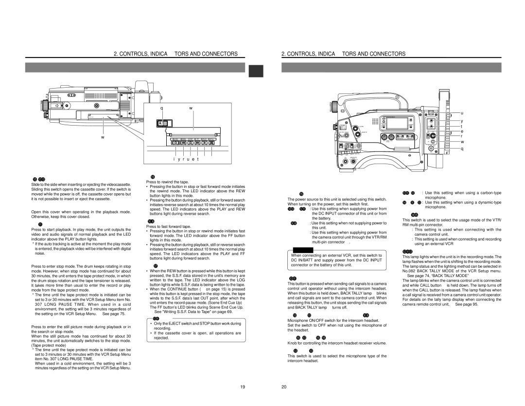
1 | [EJECT] switch |
| Slide to the side when inserting or ejecting the videocassette. |
| Sliding this switch opens the cassette cover. If the switch is |
| moved while the power is off, the cassette cover opens but |
| it is not possible to insert or eject the cassette. |
2 Operation cover | |
| Open this cover when operating in the playback mode. |
| Otherwise, keep this cover closed. |
3 | [PLAY] button |
| Press to start playback. In play mode, the unit outputs the |
| video and audio signals of normal playback and the LED |
| indicator above the PLAY button lights. |
*If the auto tracking is active at the moment the play mode is entered, the playback video will be interfered with digital noise.
4 | [STOP] button |
| Press to enter stop mode. The drum keeps rotating in stop |
| mode. However, when stop mode has continued for about |
| 30 minutes, the unit enters the tape protect mode, in which |
| the drum stops rotation and the tape tensioner is released. |
| It takes more time than usual to enter the record or play |
| mode from the tape protect mode. |
*The time until the tape protect mode is initiated can be set to 3 or 30 minutes with the VCR Setup Menu item No. 307 LONG PAUSE TIME. When used in a cold environment, the setting will be 3 minutes regardless of the setting on the VCR Setup Menu. ☞ See page 75.
5 | [STILL] button |
| Press to enter the still picture mode during playback or in |
| the search or stop mode. |
| When the still picture mode has continued for about 30 |
| minutes, the unit automatically switches to the stop mode. |
| (Tape protect mode) |
*The time until the tape protect mode is initiated can be set to 3 minutes or 30 minutes with the VCR Setup Menu item No. 307 LONG PAUSE TIME.
When used in a cold environment, the setting will be 3 minutes regardless of the setting on the VCR Setup Menu.
| Press to rewind the tape. | |
| • | Pressing the button in stop or fast forward mode initiates |
|
| the rewind mode. The LED indicator above the REW |
|
| button lights in this mode. |
| • | Pressing the button during playback, still or forward search |
|
| initiates reverse search at about 10 times the normal play |
|
| speed. The LED indicators above the PLAY and REW |
|
| buttons light during reverse search. |
7 | [FF] button | |
| Press to fast forward tape. | |
| • | Pressing the button in stop or rewind mode initiates fast |
|
| forward mode. The LED indicator above the FF button |
|
| lights in this mode. |
| • | Pressing the button during playback, still or reverse search |
|
| initiates forward search at about 10 times the normal play |
|
| speed. The LED indicators above the PLAY and FF |
|
| buttons light during forward search. |
8 | [LOG] button | |
| • | When the REW button is pressed while this button is kept |
|
| pressed, the S.S.F. data stored in the unit’s memory are |
|
| written to the tape. The LED indicator above the LOG |
|
| button lights while S.S.F. data is being written to the tape. |
| • | When the CONTINUE button (F on page 15) is pressed |
|
| while this button is kept pressed in the stop mode, the tape |
|
| winds to the S.S.F. data’s last OUT point, after which the |
|
| unit enters the |
|
| The FF button’s LED blinks during Scene End Cue Up. |
☞See "Writing S.S.F. Data to Tape" on page 69.
CAUTION:
•Only the EJECT switch and STOP button work during recording.
•If the cassette cover is open, all operations are
rejected.
1 | [POWER] power source setting switch | |||
| The power source to this unit is selected using this switch. | |||
| When turning on the power, set this switch first. | |||
| DC IN/BATT : Use this setting when supplying power from | |||
|
|
| the DC INPUT connector of this unit or from | |
|
|
| the battery. | |
| OFF | : Use this setting when not supplying power to | ||
|
|
| this unit. | |
| RM | : Use this setting when supplying power from | ||
|
|
| the camera control unit through the VTR/RM | |
|
|
| ||
|
|
| ||
|
| CAUTION: |
| |
|
|
|
| |
| When connecting an external VCR, set this switch to | |||
| DC IN/BATT and supply power from the DC INPUT | |||
| connector or the battery of this unit. | |||
2 | [CALL] button |
| This button is pressed when sending call signals to a camera |
| control unit operator without using the intercom headset. |
| When this button is held down, BACK TALLY lamp 7 blinks |
| and call signals are sent to the camera control unit. When |
| releasing this button, the unit stops sending the call signals |
| and BACK TALLY lamp 7 turns off. |
3 | [INCOM MIC] intercom microphone ON/OFF switch |
| Microphone ON/OFF switch for the intercom headset. |
| Set the switch to OFF when not using the microphone of |
| the headset. |
4 | [INTERCOM LEVEL] intercom receiver volume |
| Knob for controlling the intercom headset receiver volume. |
5 | [INCOM MIC] intercom microphone setting switch |
| This switch is used to select the microphone type of the |
| intercom headset. |
| CARBON : | Use this setting when using a | |
|
|
| microphone. |
| DYNAMIC : | Use this setting when using a | |
|
|
| microphone. |
6 | [MODE] setting switch | ||
| This switch is used to select the usage mode of the VTR/ | ||
| RM | ||
| RM : | This setting is used when connecting with the | |
|
| camera control unit. | |
| VTR : | This setting is used when connecting and recording | |
|
| using an external VCR | |
7 BACK Tally lamp | |||
| This lamp lights when the unit is in the recording mode. The | ||
| lamp flashes when the unit is shifting to the recording mode. | ||
| The lamp status and the lighting method can be selected in | ||
| No.082 BACK TALLY MODE of the VCR Setup menu. | ||
☞See page 74, “BACK TALLY MODE”
The lamp blinks when the camera control unit is connected and while CALL button 2 is held down. The lamp turns off when the CALL button is released. The lamp flashes when a call signal is received from a camera control unit operator. For details on the tally lamp display when connecting the camera remote control unit, ☞ See page 95.
19 | 20 |