2. CONTROLS, INDICATORS AND CONNECTORS
2. CONTROLS, INDICATORS AND CONNECTORS
2-2 Right Side Section [Cont’d]
• | The iris is placed in automatic mode even if the iris |
| mode switch of the lens is in manual. |
• | The gain will vary continuously to the maximum of |
| +12 dB. The shutter speed will vary continuously to |
AUTO KNEE function When shooting a foreground subject, such as a human being, etc., with a
2-2 Right Side Section (Cont'd)
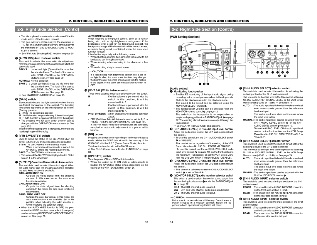
[VCR Setting Section]
the minimum of 1/240 (U MODEL)/1/200 (E MOD- |
EL) of a second. |
☞ See "Full Auto Shooting (FAS) function" on page 90. |
background image will be blurred with white. In such a case, a clearer background is obtained when the auto knee function is used. It is effective especially in the following cases:
OPERATE/WARNING |
LIGHT |
|
| 5 | 6 | 7 | 8 |
AUDIO |
|
|
| ||
LEVEL |
|
|
| ||
| |||||
|
| ||||
|
|
| AUTO |
| FRONT |
|
|
| MANUAL |
| REAR |
8 | [AUTO IRIS] Auto iris level switch |
| This switch selects the automatic iris adjustment |
| reference value according to the condition in which the |
| camera is used. |
| BACK L : Under back light (Opens the iris more than |
| the standard level. The level of iris can be |
| set in SPOT L/BACK L of the OPERATION |
| MENU screen.) ☞ See page 79 |
| NORMAL: Normal condition |
•When shooting a human being indoors with a view to the landscape out through a window.
•When shooting a human being in the shade on a fine day.
•When shooting a
CAUTION:
If a fast moving
FILTER
ALARM
SHUTTER STATUS | MONITOR |
MENU
NG OPERATE
ONOFF
RESET |
|
MONITOR | COUNTER |
SELECT |
LEVEL
SEE
INSTR-
UCTION
MANUAL
LITHIUM BATT. 
H 0
| AUDIO SELECT |
| AUDIO INPUT | |||
VTR SELECT TC GENE. |
| MENU | ||||
INT |
|
| CONTINUE | |||
| PRST | REC |
|
| ||
PARA |
| FREE |
|
| ||
EXT |
| REGEN |
|
|
| |
CAM AUX | GROUP | ITEM | SELECT | DATA SET | ||
HOLD | SHIFT | ADVANCE | PRESET | |||
|
| |||||
VTR INPUT
9B C D E F A
G
| SPOT L : Under spotlight (Closes the iris more than | |
|
| the standard level. The level of iris can be |
|
| set in SPOT L/BACK L of the OPERATION |
|
| MENU screen.) ☞ See page 79 |
| ☞ See "SWITCH FUNCTIONS" on page 90. | |
9 | [GAIN] switch | |
| Electronically boosts the light sensitivity when there is | |
| insufficient illumination on the subject. The boosting | |
| level differs depending on the switch position as follows: | |
| (Factory presets) | |
| L | : 0 dB (no boosting is applied) |
| M : 9 dB (boosted to approximately 3 times the original) | |
| H | : 18 dB (boosted to approximately 8 times the original) |
| • | The boosting level for each switch position can be |
|
| changed with the OPERATION menu screen. (☞ See |
|
| page 79.) |
| The more the boosting level is increased, the more the | |
| resulting image will be noisy. | |
0 | [VTR SAVE/STBY] switch | |
| Used to select the status of the | |
| power is turned ON and a videocassette is loaded. | |
| STBY: The | |
|
| When a recordable videocassette is loaded, the |
|
| |
| SAVE: The | |
| • | The status of the |
|
| screen 1 in the viewfinder. |
! | [OUTPUT] Color bar/Camera/Auto knee switch | |
| This switch is used to select the output signal. When | |
| the video signal from the shooting camera is selected, | |
| the auto knee function is available. | |
| CAM. AUTO KNEE ON: | |
|
| Outputs the video signal from the shooting |
|
| camera. In this case mode, the auto knee |
|
| function is available. |
| CAM. AUTO KNEE OFF: | |
|
| Outputs the video signal from the shooting |
|
| camera. In this mode, the auto knee function is |
|
| not available. |
| BARS. AUTO KNEE OFF: | |
|
| Outputs the color bar signal. In this mode, the |
|
| auto knee function is not available. Set to this |
|
| position when adjusting the video monitor or |
|
| when recording the color bar signal. |
| • | When the AUTO KNEE function is OFF, the point |
|
| where the KNEE function takes effect (knee point) |
|
| can be set using KNEE POINT in PROCESS MENU |
|
| screen. ☞ See page 80 |
OFF.
@ [WHT.BAL] White balance switch Three white balance modes are selectable with this switch.
B: If white balance is performed with the switch in this position, it will be memorised into B.
A: If white balance is performed with the switch in this position, it will be memorised into A.
PRST (PRESET) : A
•FAW
# | [NG] button |
| Pressing this button while recording or in the |
| mode deletes the S.S.F. data stored in the memory of the |
| |
| This function is only valid in the MARK mode. |
| ☞ See “S.S.F. (Super Scene Finder) FUNCTION” on page |
| 68. |
$ | [OPERATE] switch | |
| Turn the power ON and OFF with this switch. | |
| • | When this switch set to ON while a videocassette is |
|
| loaded, the |
|
| setting of the VTR (SAVE/STBY) switch 0. |
1 2 3
[Audio setting] 1 Monitoring loudspeaker
| • | Enables EE monitoring of the input audio signal during |
|
| recording, in the |
|
| Outputs the playback sound in the playback mode. |
|
| The sound to be output can be selected using the |
|
| MONITOR SELECT switch 4. |
| • | The loudspeaker volume can be adjusted with the |
|
| MONITOR volume control 2 on page 12. |
|
| The audio from the loudspeaker is not output when an |
|
| earphone is plugged into the EARPHONE jack 2 on page |
|
| 22. The warning alarm tones are also output through this |
|
| loudspeaker. |
| ☞ See “ALARM INDICATIONS” on pages 96. | |
2 | [CH1 AUDIO LEVEL] CH1 audio input level control | |
| Adjust the audio input level of the CH1 audio channel with | |
| this control. | |
| • | To use this control, set the CH1 AUDIO SELECT switch |
|
| 5 to “MANUAL”. |
|
| This control works regardless of the setting of the VCR |
|
| Setup Menu item No. 246 CH1 FRONT VR ENABLE. |
|
| To use this control, set the AUDIO LEVEL |
|
| input level control (7 on page 10) on the front section to |
|
| the maximum (10) position, or set the VCR Setup Menu |
|
| item No. 246 CH1 FRONT VR ENABLE to “DISABLE”. |
3 | [CH2 AUDIO LEVEL] CH2 audio input level control | |
| Adjust the audio input level of the CH2 audio channel with | |
| this control. | |
| • | This control is valid only when the CH2 AUDIO SELECT |
|
| switch 6 is set to "MANUAL". |
4 | [MONITOR SELECT] audio monitor selector switch | |
| This switch is used to select the monitor sound output from | |
| the monitoring loudspeaker 1 or via the EARPHONE jack | |
| 2 on page 22. | |
| ||
| MIX : CH1 and CH2 channel audio are output mixed. | |
| ||
| CAUTION: | |
Make sure to move switches all the way. Do not leave a | ||
switch stopped in a midway position. Noise will be | ||
generated and operation irregularities will occur. | ||
5 |
| |
| This switch is used to select the method for adjusting the | |
| audio input level of the | |
| The reference audio input level to the tape can be set using | |
| No. 257 AUDIO REF. SIGNAL LEVEL in the VCR Setup | |
| Menu screen | |
| AUTO | : The audio input level is held at the reference level |
|
| even when sounds greater than the reference |
|
| level are input. |
|
| The audio input level does not increase when |
|
| the input level is low. |
| MANUAL : The audio input level can be adjusted with the | |
|
| |
|
| AUDIO LEVEL control 7 on page 10. |
|
| To use the AUDIO LEVEL |
|
| control on the front section, set the VCR Setup |
|
| Menu item No. 246 CH1 FRONT VR ENABLE to |
|
| “ENABLE”. |
6 |
| |
| This switch is used to select the method for adjusting the | |
| audio input level of the | |
| The reference audio input level to the tape can be set using | |
| No. 257 AUDIO REF. SIGNAL LEVEL in the VCR Setup | |
| Menu screen | |
| AUTO | : The audio input level is held at the reference level |
|
| even when sounds greater than the reference |
|
| level are input. |
|
| The audio input level does not increase when |
|
| the input level is low. |
| MANUAL : The audio input level can be adjusted with the | |
|
| |
7 |
| |
| This switch is used to select the input section of the CH1 | |
| audio channel. | |
| FRONT | : The sound from the AUDIO IN FRONT connector |
|
| on the front side section is input. |
| REAR | : The sound from the AUDIO IN REAR connector |
|
| on the rear side section is input. |
8 |
| |
| This switch is used to select the input section of the CH2 | |
| audio channel. | |
| FRONT | : The sound from the AUDIO IN FRONT connector |
|
| on the front side section is input. |
| REAR | : The sound from the AUDIO IN REAR connector |
|
| on the rear side section is input. |
13 | 14 |