| 13. FEATURES OF THE CAMERA SECTION |
| Connecting the camera remote control unit (Cont’d) |
14. OTHERS |
|
Operation
Set the POWER switch of the camera remote control unit to ON. About 30 seconds after turning the power on, the camera remote control unit will be operative.
Memo:
After the POWER switch is turned on, the camera remote control unit takes about 30 seconds to prepare for correct communication with this unit.
■Unavailable functions
The following functions are unavailable from the camera remote control unit.
•
•
ABL
Memo:
■TALLY lamp display when the camera remote control unit is connected.
![]() BACK TALLY lamp
BACK TALLY lamp
When the camera remote control unit is connected, the viewfinder (VF) FRONT TALLY lamp, REC/ALARM lamp inside the viewfinder and the BACK TALLY lamp are displayed as
shown below. |
BACK TALLY |
VF |
Warnings concerning problems with the unit are provide in the form of indicators, display indications and monitor tones. | ||||||||||
The warnings are of the following two types. |
|
|
|
|
|
|
|
|
| |
• Alarm indications : These indications are given to provide warning on the status of the unit, for example when the tape or battery pack should be replaced. | ||||||||||
• Error code display : In case an error occurs during operation, the unit | ||||||||||
on the counter display. When this happens, the unit stops operation automatically or ejects the videocassette. | ||||||||||
CAUTION: |
|
|
|
|
|
|
|
|
|
|
Alarms and error codes of the external VCR connected to the VTR/RM | ||||||||||
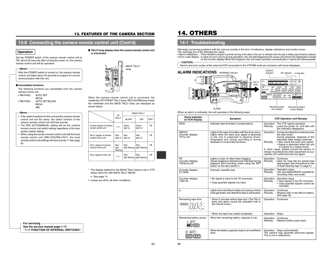
ALARM INDICATIONS | WARNING indicator | SERVO |
|
|
|
|
|
|
| |
indicator |
| RF indicator |
| Li indicator | ||||||
| TALLY | CH 1 |
|
|
| OVER | AUTO OFF | DEW | ||
|
| 40 30 | 20 | 10 | 0 dB |
|
|
|
| |
| lamp | CH 2 |
|
|
| OVER | SERVO RF | L i | ||
|
| 32k | 48k |
| SLAVE | PB | NDF | HOLD | ||
|
| AUD LOCK | SP |
|
|
|
|
|
|
|
|
| MENU | WIDE |
| H | M |
|
| S | F |
|
|
|
|
|
| |||||
|
| REMAIN |
|
| REV FWD | E | BATT F | |||
|
|
|
|
|
|
|
|
| ||
OPERATE |
|
|
| H | M |
|
|
|
|
|
ALARM |
| Remaining tape | Remaining battery | |||||||
| time display |
| power display | |||||||
When an alarm is indicated, the unit operates in the following ways. |
|
|
|
|
|
|
|
|
| |
•If the switch functions for this unit and the camera remote control unit are the same, the switch function of the camera remote control unit will have priority.
•The IRIS AUTO/MANUAL setting will be the camera remote control unit switch setting regardless of the lens section switch setting.
•When using the camera remote control unit with the local remote control unit
| TALLY | BLINK* | ON* | OFF* |
|
| |||
Preview signals of camera |
| Green | Green | Off |
remote control unit |
| light on | light on |
|
TALLY signals of camera | Red | Red | Red | Off |
remote control unit | light on | light on | light on |
|
CALL signals of camera | Red | Red | Red | Off |
remote control unit | light | light flashing | light flashing |
|
| flashing |
|
|
|
CALL signals of this unit |
| Red | Red | Off |
|
| light flashing | light flashing |
|
Alarm Indicator on VCR Display
DEW
SERVO (Counter display) “SYnc inh”
RF |
(Counter display) |
“HEAd CLoG” |
Symptom Indicates dew formation (condensation).
Lights in the case of troubles with the drum servo. Lights when the input sync signal is disturbed or the unit is subjected to physical shock. (Displayed only during recording or during playback of unrecorded portions.)
Lights in case of video head clogging. (Head clogging is detected and indicated during playback and recording check using the RET button on the lens section.)
| VCR Operation and Remedy |
Operation : The VTR rejects operation. | |
Remedy | : Leave the power on, and wait until |
| the indication disappears. |
Operation : During recording the mode becomes | |
| the stop mode. |
| During playback, playback of the |
Remedy | disturbed video image continues. |
: • Also check the input sync signal. | |
| • Signal is disturbed when the unit |
| is subject to a violent shock. |
In other cases, please consult the person in | |
charge of professional video equipment at your | |
nearest | |
Operation : Continues. | |
Remedy | : Clean the head with the special head |
| cleaning tape. (See “Precautions for Use |
| of Head Cleaning Tape” on page 8.) |
* | The display method for the BACK TALLY lamp is set in VTR |
| Setup menu No. 082 BACK TALLY MODE. |
| ☞ See page 74 |
• | Lamps are off for all other conditions. |
(Counter display) |
|
Pc TAPE |
|
(Counter display) |
|
1394 inh |
|
Li |
|
Remaining tape time |
|
REMAIN |
|
H | M |
Improper cassette type
•No signal is input to the DV connector.
•
Lights when the lithium battery for backup of time code generator and date/time data is exhausted.
*About 2 minutes before tape end. (The TALLY lamp and alarm sound are activated only in the record mode.)
Operation : Operation stops. | |
Remedy | : Use recordable MiniDV cassette for |
| recording video and audio. |
Operation : Operation stops. | |
Remedy | : • Input signals to the DV connector. |
| • |
| recorded. |
Operation : Continues. | |
Remedy | : Replace with a new lithium battery. |
| See page 36. |
Operation : Continues. | |
| For servicing | |
→ | See the service manual page | |
“1.11 FUNCTION OF INTERNAL SWITCHES”. | ||
|
|
|
|
|
|
| * When the tape has ended completely. | Operation : Stops. | ||
Remaining battery power When the remaining battery capacity is low. | Operation : Continues. | ||||||||
| E |
| BATT |
| Remedy | : Replace battery pack early. | |||
|
|
|
|
| |||||
|
|
|
|
|
| When the battery capacity drops to an insufficient | Operation : Stops automatically. | ||
|
|
|
|
|
| ||||
|
|
|
|
|
| ||||
E | BATT | ||||||||
level. | The camera may generate abnormal signals. | ||||||||
|
|
|
|
|
|
| This is not a malfunction. | ||
95 | 96 |