1-5 Videocassette to be Used
1. INTRODUCTION
2. CONTROLS, INDICATORS AND CONNECTORS
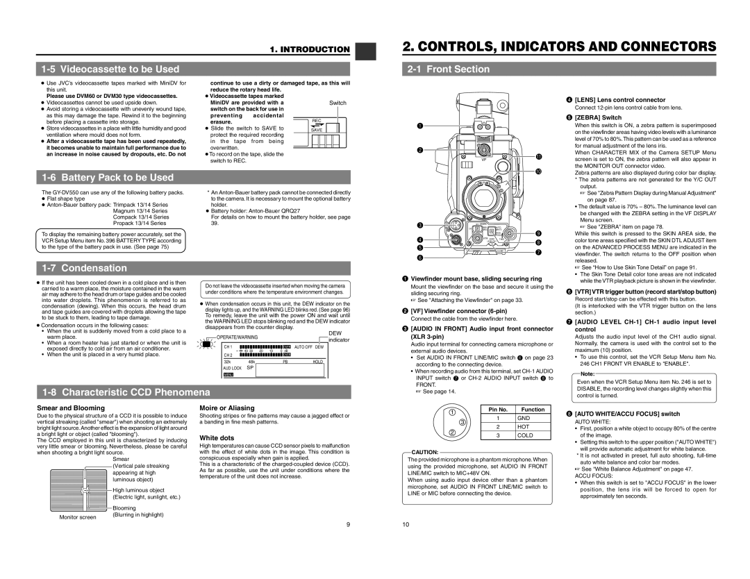
2-1 Front Section
●Use JVC’s videocassette tapes marked with MiniDV for this unit.
Please use DVM60 or DVM30 type videocassettes.
●Videocassettes cannot be used upside down.
●Avoid storing a videocassette with unevenly wound tape, as this may damage the tape. Rewind it to the beginning before placing a cassette into storage.
●Store videocassettes in a place with little humidity and good ventilation where mould does not form.
●After a videocassette tape has been used repeatedly, it becomes unable to maintain full performance due to an increase in noise caused by dropouts, etc. Do not
1-6 Battery Pack to be Used
continue to use a dirty or damaged reduce the rotary head life.
●Videocassette tapes marked MiniDV are provided with a switch on the back for use in
preventing accidental erasure.
●Slide the switch to SAVE to protect the required recording in the tape from being overwritten.
●To record on the tape, slide the switch to REC.
tape, as this will
Switch
REC
SAVE
q |
|
w |
|
VF | ! |
| |
| ! |
4 | [LENS] Lens control connector |
| Connect |
5 | [ZEBRA] Switch |
| When this switch is ON, a zebra pattern is superimposed |
| on the viewfinder areas having video levels with a luminance |
| level of 70% to 80%.This pattern can be used as a reference |
| for manual adjustment of the lens iris. |
| When CHARACTER MIX of the Camera SETUP Menu |
| screen is set to ON, the zebra pattern will also appear in |
| the MONITOR OUT connector video. |
| Zebra patterns are also displayed during color bar display. |
| * The zebra patterns are not generated for the Y/C OUT |
| output. |
The
●
To display the remaining battery power accurately, set the VCR Setup Menu item No. 396 BATTERY TYPE according to the type of the battery pack in use. (See page 75)
*An
●Battery holder:
For details on how to mount the battery holder, see page
39.
e | PUSH |
| OFF ZEBRA |
|
|
ON | SKIN | AUTO |
| ||
|
| AREA | WHITE |
| |
|
|
|
| ACCU | o |
|
|
|
| FOCUS | |
r |
|
| VTR AUDIO | TAKE | i |
|
| LEVEL | |||
t |
|
| 10 |
| |
|
|
|
| u | |
y |
|
|
|
| |
|
|
|
|
| |
☞ See "Zebra Pattern Display during Manual Adjustment" |
on page 87. |
• The default value is 70% – 80%. The luminance level can |
be changed with the ZEBRA setting in the VF DISPLAY |
Menu screen. |
☞ See "ZEBRA" item on page 78. |
While this switch is pressed to the SKIN AREA side, the |
color tone areas specified with the SKIN DTL ADJUST item |
on the ADVANCED PROCESS MENU are indicated in the |
viewfinder. The switch returns to the OFF position when |
released. |
Condensation | |
● If the unit has been cooled down in a cold place and is then | |
carried to a warm place, the moisture contained in the warm | |
air may adhere to the head drum or tape guides and be cooled | |
into water droplets. This phenomenon is referred to as | |
condensation (dewing). When this occurs, the head drum | |
and tape guides are covered with droplets allowing the tape | |
to be stuck to them, leading to tape damage. | |
● Condensation occurs in the following cases: | |
•When the unit is suddenly moved from a cold place to a warm place.
•When a room heater has just started or when the unit is exposed directly to cold air from an air conditioner.
•When the unit is placed in a very humid place.
Do not leave the videocassette inserted when moving the camera | ||||||||||||||||
under conditions where the temperature environment changes. | ||||||||||||||||
● When condensation occurs in this unit, the DEW indicator on the | ||||||||||||||||
display lights up, and the WARNING LED blinks red. (See page 96) | ||||||||||||||||
To remedy, leave the unit with the power ON and wait until | ||||||||||||||||
the WARNING LED stops blinking red and the DEW indicator | ||||||||||||||||
disappears from the counter display. | DEW | |||||||||||||||
|
|
| OPERATE/WARNING |
|
|
|
|
|
|
|
| |||||
|
|
|
|
|
|
|
|
|
|
| indicator | |||||
|
|
|
|
|
|
|
|
|
|
|
|
|
|
|
| |
|
|
|
|
|
|
|
|
|
|
|
|
|
|
|
|
|
|
|
| CH 1 |
|
|
|
|
|
|
|
|
|
| OVER |
| AUTO OFF DEW |
|
|
|
| 40 30 |
| 20 | 10 |
| 0 dB | |||||||
|
|
|
|
|
|
| ||||||||||
|
|
| CH 2 |
|
|
|
|
|
|
|
|
|
| OVER |
|
|
|
|
|
|
|
|
|
|
|
|
|
|
| ||||
|
|
| 32k |
|
| 48k |
|
|
|
|
|
| PB | HOLD | ||
|
|
| AUD LOCK |
| SP |
|
|
|
|
|
|
|
|
| ||
MENU
1 Viewfinder mount base, sliding securing ring | |
| Mount the viewfinder on the base and secure it using the |
| sliding securing ring. |
| ☞ See "Attaching the Viewfinder" on page 33. |
2 | [VF] Viewfinder connector |
| Connect the cable from the viewfinder here. |
3 | [AUDIO IN FRONT] Audio input front connector |
| (XLR |
| Audio input terminal for connecting camera microphone or |
| external audio devices. |
• | Set AUDIO IN FRONT LINE/MIC switch 6 on page 23 |
| according to the connecting device. |
• | When recording audio from this terminal, set |
| INPUT switch 7 or |
| FRONT. |
| ☞ See “How to Use Skin Tone Detail” on page 91. | ||
| • The Skin Tone Detail color tone areas are not indicated | ||
| while the VTR playback picture is shown in the viewfinder. | ||
6 | [VTR] VTR trigger button (record start/stop button) | ||
| Record start/stop can be effected with this button. | ||
| (It is interlocked with the VTR trigger button on the lens | ||
| section.) | ||
7 | [AUDIO LEVEL | ||
| control | ||
| Adjusts the audio input level of the CH1 audio signal. | ||
| Normally, the camera is used with the control set to the | ||
| maximum (10) position. | ||
| • To use this control, set the VCR Setup Menu item No. | ||
| 246 CH1 FRONT VR ENABLE to "ENABLE". | ||
|
|
| |
|
| Note: |
|
| Even when the VCR Setup Menu item No. 246 is set to | ||
Characteristic CCD Phenomena |
☞ See page 14. |
DISABLE, the recording level changes slightly when this |
control is turned. |
Smear and Blooming Due to the physical structure of a CCD it is possible to induce vertical streaking (called "smear") when shooting an extremely bright light source. Another effect is the expansion of light around a bright light or object (called "blooming"). The CCD employed in this unit is characterized by inducing very little smear or blooming. Nevertheless, please be careful when shooting a bright light source. Smear (Vertical pale streaking appearing at high ![]() luminous object)
luminous object)
High luminous object |
(Electric light, sunlight, etc.) |
| Blooming |
Monitor screen | (Blurring in highlight) |
|
Moire or Aliasing Shooting stripes or fine patterns may cause a jagged effect or a banding in fine mesh patterns.
White dots High temperatures can cause CCD sensor pixels to malfunction with the effect of white dots in the image. This condition is conspicuous especially when gain is applied. This is a characteristic of the
1 | Pin No. | Function | |
1 | GND | ||
| |||
| 3 | HOT | |
2 | 2 | ||
3 | COLD | ||
| |||
CAUTION: |
|
| |
The provided microphone is a phantom microphone. When | |||
using the provided microphone, set AUDIO IN FRONT | |||
LINE/MIC switch to MIC+48V ON. |
| ||
When using audio input device other than a phantom | |||
microphone, set AUDIO IN FRONT LINE/MIC switch to | |||
LINE or MIC before connecting the device. |
| ||
8 | [AUTO WHITE/ACCU FOCUS] switch | |
| AUTO WHITE: | |
| • | First, position a white object to occupy 80% of the centre |
|
| of the image. |
| • | Setting this switch to the upper position ("AUTO WHITE") |
|
| will provide automatic adjustment for white balance. |
| * It is not activated in preset, full auto shooting, | |
|
| auto white balance and color bar modes. |
| ☞ See "White Balance Adjustment" on page 47. | |
| ACCU FOCUS: | |
| • | When this switch is set to "ACCU FOCUS" in the lower |
|
| position, the lens iris will be forced to open for |
|
| approximately ten seconds. |
9 | 10 |