| 2. CONTROLS, INDICATORS AND CONNECTORS | ||
|
| ||
| PUSH |
|
|
| 7 |
|
|
| VTR/RM |
| DV CAMCORDER |
|
| ||
|
|
| |
8 |
|
|
|
| PROMPTER |
|
|
| OUTPUT |
|
|
9 |
|
| GENLOCK/AUX IN |
Y/C OUT MONITOR OUT | LINE OUT | VIDEO OUT | |
| |||
|
|
| REMOTE |
|
|
| AUDIO IN |
|
|
| FRONT |
| TC IN | TC OUT | LENS |
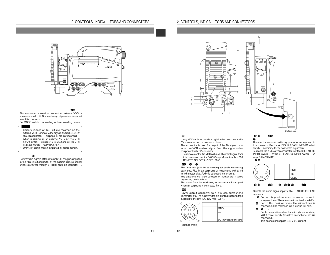
8 | [VTR/RM] VTR/RM |
| This connector is used to connect an external VCR or |
| camera control unit. Camera image signals are outputted |
| from this connector. |
| Set MODE switch 6 according to the connecting device. |
| Memo: |
2. CONTROLS, INDICATORS AND CONNECTORS
|
|
|
|
| ||
|
|
|
|
| !0 |
|
|
|
|
|
| PUSH |
|
|
|
|
| o |
|
|
|
|
|
|
| VTR/RM | DV CAMCORD |
|
|
|
|
|
| |
|
|
|
|
|
| |
|
|
|
| t | PROMPTER |
|
|
|
|
| OUTPUT |
| |
|
|
|
| y | Y/C OUT MONITOR OUT LINE OUT | |
|
|
|
|
| ||
|
|
|
|
|
| !1 |
q | DV LINE | MIC | LINE MICINTERCOM |
|
| REMOT |
| +48V | +48V |
|
|
| |
| ON | ON | DC INPUT |
|
| |
w | EARPHONE |
| FRONT | TC IN | TC OUT | |
|
| AUDIO IN |
|
|
| |
| DC |
| REAR |
|
|
|
| OUTPUT |
|
|
|
|
|
e |
|
|
|
|
|
|
|
| r | u | i |
|
|
|
|
|
|
|
| BREAKER |
•Camera images of this unit are recorded on the external VCR. Compost video signals from GENLOCK/ AUX IN connector 8 on page 18 are not recorded.
•When recording on an external VCR, set the VTR INPUT switch 9 on page 15 to CAM and set the VTR SELECT switch = to PARA or EXT.
•Only CH1 audio can be outputted for audio signals.
9 | [PROMPTER OUTPUT] prompter output connector |
| Return video signals of the external VCR or signals inputted |
| to the AUX input connector of the camera remote control |
| unit are outputted through VTR/RM |
1 | [DV] connector |
| Using a DV cable (optional), a digital video component with |
| DV connector can be connected here. |
| This connector is used for output of the DV signal or to |
| input the VCR control signal from the digital video |
| component with DV connector. |
| • To remote control the VCR with a VCR control signal from |
| this connector, set the VCR Setup Menu item No. 050 |
| REMOTE SELECT to "IEEE1394". |
2 | [EARPHONE] earphone jack |
| This is a |
| earphone. Plug in an earphone or headphone with a 3.5 |
| mm diameter plug. Audio is outputted in monaural. |
| The earphone can also be used to monitor alarm tones |
| depending on situations. |
| The sound from the monitoring loudspeaker is interrupted |
| when an earphone is connected here. |
3 | [DC OUTPUT] connector |
| Power output connector to a wireless microphone |
| transmitter, etc.The supply voltage is identical to the voltage |
| supplied to the unit (DC 12V max. 0.1 A). |
|
|
| Bottom side |
4 | [AUDIO IN REAR] audio input rear connector (XLR | ||
|
|
| |
| Connect the external audio equipment or microphone to | ||
| this connector. Set the AUDIO IN REAR LINE/MIC select | ||
| switch 5 according to the connected equipment. | ||
| To record the audio of this connector, set the | ||
| INPUT switch 7 or the | ||
| page 14 to "REAR". |
| |
| (AUDIO IN connector) |
| |
|
|
|
|
|
| No. | Signal |
1GND
2 |
| 1 | 2 | HOT |
|
|
| ||
| 3 |
| 3 | COLD |
|
|
|
5 | [AUDIO IN REAR LINE/MIC] AUDIO IN REAR select |
| switch |
| Selects the audio signal input to the 4 AUDIO IN REAR |
| connector. |
| LINE : Set to this position when connected to audio |
| equipment, etc. The reference input level is +4 dBs. |
4 | 1 |
3 | 2 |
(Surface profile) | |
No.
1
2
3
4
Signal
GND
—
—
DC +12V (power through)
MIC | : Set to this position when the microphone is |
| connected. The reference input level is |
MIC +48V ON: | |
| Set to this position when the microphone requiring |
| +48 V power supply (phantom microphone, etc.) is |
| connected. |
| This connector supplies +48 V DC current. |
21 | 22 |