CONTROLS, INDICATORS AND CONNECTORS
Indications on the LCD Monitor and in the Viewfinder (Cont’d)
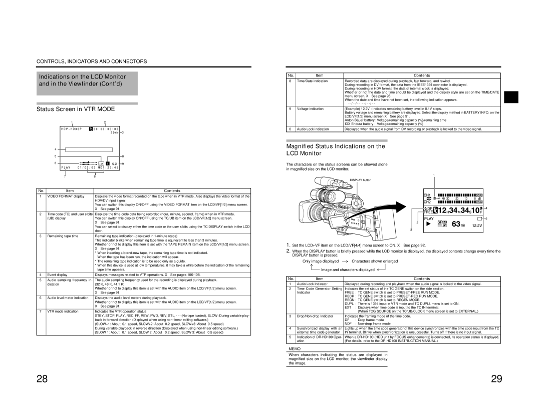
Status Screen in VTR MODE
1 | 2 |
| 3 |
No. | Item | Contents |
8 | Time/Date indication | Recorded data are displayed during playback, fast forward, and rewind. |
|
| During recording in DV format, the data from the IEEE1394 connector is displayed. |
|
| During recording in HDV format, the data of internal clock is displayed. |
|
| Whether or not the date and time should be displayed and the display style are set on the TIME/DATE |
|
| menu screen. X See page 95. |
|
| When the date and time have not been set, the following indication appears. |
|
| - |
9 | Voltage indication | (Example) 12.2V : Indicates remaining battery level in 0.1V steps. |
|
| Battery voltage and remaining battery are displayed. Select the display method in BATTERY INFO. on the |
|
| LCD/VF[1/2] menu screen X See page 91. |
|
| Anton Bauer battery: Voltage/remaining capacity (%)/remaining time |
|
| IDX Endura battery : Voltage/remaining capacity (%) |
0 | Audio Lock indication | Displayed when the audio signal from DV recording or playback is locked to the video signal. |
4 |
|
|
|
|
|
|
|
|
|
|
|
|
|
|
|
|
|
|
|
|
|
|
|
|
|
|
|
|
|
|
|
|
|
| |
5 |
|
|
|
|
|
|
| 0 | |||||||||
6 |
|
|
|
|
|
|
|
|
|
|
|
|
|
|
|
| 9 |
|
|
|
|
|
|
|
|
|
|
|
|
|
|
| |||
|
|
|
|
|
|
|
|
|
|
|
|
|
|
|
| ||
|
|
|
|
|
|
|
|
|
|
|
|
|
|
|
|
|
|
7 |
| 8 |
|
|
|
|
|
|
|
|
| ||||||
No. | Item | Contents |
1 | VIDEO FORMAT display | Displays the video format recorded on the tape when in VTR mode. Also displays the video format of the |
|
| HDV/DV input signal. |
|
| You can switch this display ON/OFF using the VIDEO FORMAT item on the LCD/VF[1/2] menu screen. |
|
| X See page 91. |
2 | Time code (TC) and user’s bits | Displays the time code data being recorded (hour, minute, second, frame) when in VTR mode. |
| (UB) display | You can switch this display ON/OFF using the TC/UB item on the LCD/VF[1/2] menu screen. |
|
| X See page 91. |
|
| You can select to display either the time code or the user’s bits using the TC DISPLAY switch in the LCD |
|
| door. |
3 | Remaining tape time | Remaining tape indication (displayed in |
|
| This indicator blinks when remaining tape time is equivalent to less than 3 minutes. |
Magnified Status Indications on the
LCD Monitor
The characters on the status screens can be showed alone in magnified size on the LCD monitor.
DISPLAY button
2
3
1
![]()
![]()
![]()
![]()
![]()
![]() 4
4
266S DD ![]() 5
5
|
| Whether or not to display this item is set with the TAPE REMAIN item on the LCD/VF[1/2] menu screen. |
|
| X See page 91. |
|
| * When inserting a |
|
| When the tape has been run, the indication will appear. |
|
| * The remaining tape indication is to be used only as a guide. |
|
| * When this device is used at low temperatures, it may take a while before the indication of the remaining |
|
| tape time appears. |
4 | Event display | Displays messages related to VTR operations. X See pages |
5 Audio sampling frequency in- | The audio sampling frequency used for the recording is displayed during playback. | |
| dication | (32 K, 48 K, 44.1 K) |
|
| Whether or not to display this item is set with the AUDIO item on the LCD/VF[1/2] menu screen. |
|
| X See page 91. |
6 Audio level meter indication | Displays the audio level meters during playback. | |
|
| Whether or not to display this item is set with the AUDIO item on the LCD/VF[1/2] menu screen. |
|
| X See page 91. |
7 | VTR mode indication | Indicates the VTR operation status |
|
| STBY, STOP, PLAY, REC, FF, REW, FWD, REV, STL, - - - (No tape loaded), SLOW: During variable play- |
|
| back in forward direction (Displayed when using |
|
| (SLOW+1: About ×0.1 speed, SLOW+2: About ×0.2 speed, SLOW+3: About ×0.5 speed) |
|
| During variable playback in reverse direction (Displayed when using |
|
| |
1.Set the LCD+VF item on the LCD/VF[4/4] menu screen to ON. X See page 92.
2.When the DISPLAY button is briefly pressed while the LCD monitor is displayed, the displayed contents change every time the DISPLAY button is pressed.
Only image displayed ![]() Characters shown enlarged
Characters shown enlarged
![]() Image and characters displayed
Image and characters displayed
No. | Item |
| Contents |
1 | Audio Lock Indicator | Displayed during recording and playback when the audio signal is locked to the video signal. | |
2 | Time Code Generator Setting | Indicates the set status of the TC GENE switch on the side section. | |
| Indicator | FREE : TC GENE switch is set to | |
|
| RECR : TC GENE switch is set to | |
|
| REGN : TC GENE switch is set to REGEN MODE. | |
|
| DUPL : There is 1394 input in VTR mode and TC DUPLI. menu is set to ON. | |
|
| EXT | : Displays when time code is input to the TC IN terminal. |
|
|
| (When TCG SOURCE on the TC/UB/CLOCK menu screen is set to EXTERNAL.) |
3 | Indicates the framing mode of the time code. | ||
|
| DF | : Drop frame mode |
|
| NDF | : |
4 | Synchronized display with an | Lights up when the time code generator of this device synchronizes with the time code input from the TC | |
| external time code generator | IN terminal. Blinks when synchronization is unsuccessful. Turns off If there is no input signal. | |
5 | Indication of | When a | |
| ation | (For details, refer to the | |
MEMO
When characters indicating the status are displayed in magnified size on the LCD monitor, the viewfinder display the image.
28 | 29 |