CONTROLS, INDICATORS AND CONNECTORS
Indications on the LCD Monitor
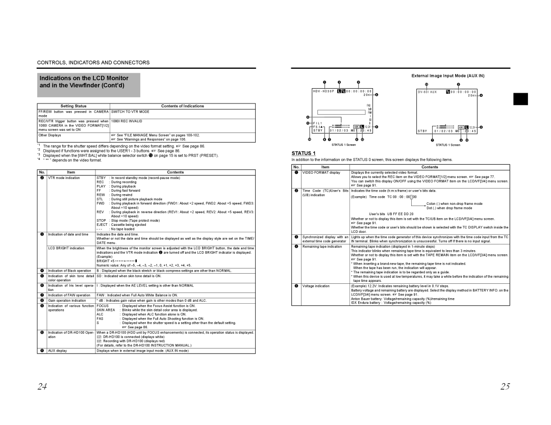
External Image Input Mode (AUX IN)
and in the Viewfinder (Cont’d)
Setting Status | Contents of Indications |
FF/REW button was pressed in CAMERA | SWITCH TO VTR MODE |
mode |
|
REC/VTR trigger button was pressed when | 1080I REC INVALID |
1080I CAMERA in the VIDEO FORMAT[1/2] |
|
menu screen was set to ON |
|
Other Displays | X See “FILE MANAGE Menu Screen” on pages |
| X See “Warnings and Responses” on page 106. |
*1 The range for the shutter speed differs depending on the video format setting. X See page 86. | |
*2 | X |
| 1 | 3 | 2 |
|
|
| 4 |
8 |
|
|
|
a |
|
|
|
|
|
| 5 |
0 | 9 7 |
| 6 b |
|
| STATUS 1 Screen | |
c 2
D V - 6 0 I A U X
![]()
![]()
![]()
![]()
![]() 4
4
![]()
![]()
![]()
![]() 5
5
76 b
STATUS 1 Screen
*3 | Displayed if functions were assigned to the USER1 - 3 buttons. | See page 86. |
Displayed when the [WHT.BAL] white balance selector switch c on page 15 is set to PRST (PRESET). | ||
*4 | “ ** ” depends on the video format. |
|
No. | Item |
| Contents |
2 | VTR mode indication | STBY | : In record standby mode |
|
| REC | : During recording |
|
| PLAY | : During playback |
|
| FF | : During fast forward |
|
| REW | : During rewind |
|
| STL | : During still picture playback mode |
|
| FWD | : During playback in forward direction (FWD1: About ×2 speed, FWD2: About ×5 speed, FWD3: |
|
|
| About ×10 speed) |
|
| REV | : During playback in reverse direction (REV1: About ×2 speed, REV2: About ×5 speed, REV3: |
|
|
| About ×10 speed) |
|
| STOP | : Stop mode (Tape protect mode) |
|
| EJECT : Cassette being ejected | |
|
| - - - | : No tape loaded |
3 | Indication of date and time | Indicates the date and time. | |
|
| Whether or not the date and time should be displayed as well as the display style are set on the TIME/ | |
|
| DATE menu. | |
| LCD BRIGHT indication | When the brightness of the monitor screen is adjusted with the LCD BRIGHT button, the date and time | |
|
| indications and the VTR mode indication 2 are turned off and the LCD BRIGHT indicator is displayed. | |
|
| (Example) | |
|
| BRIGHT +5 • • • • • + • • • • • O | |
|
| Numeric value: Any of | |
4 | Indication of Black operation | B : Displayed when the black stretch or black compress settings are other than NORMAL. | |
5 | Indication of skin tone detail | SD : Indicated when skin tone detail is ON. | |
| color operation |
|
|
6 | Indication of Iris level opera- | I : Displayed when the AE LEVEL setting is other than NORMAL | |
| tion |
|
|
7 | Indication of FAW operation | FAW : Indicated when Full Auto White Balance is ON. | |
8 | Gain operation indication | * dB : Indicates gain value when gain is other modes than 0 dB and ALC. | |
9 | Indication of various function | FOCUS | : Displayed when the Focus Assist function is ON. |
| operations | SKIN AREA : Blinks while the skin detail color area is displayed. | |
|
| ALC | : Displayed when ALC function alone is ON. |
|
| FAS | : Displayed when the Full Auto Shooting function is ON. |
|
| S | : Displayed when the shutter speed is a setting other than the default setting. |
|
|
| X See page 86. |
0 | Indication of | When a | |
| ation | [: | |
|
| [: Recording with | |
|
| (For details, refer to the | |
a | AUX display | Displays when in external image input mode. (AUX IN mode) | |
STATUS 1
In addition to the information on the STATUS 0 screen, this screen displays the following items.
No. | Item | Contents |
1 | VIDEO FORMAT display | Displays the currently selected video format. |
|
| Allows you to select the REC item on the VIDEO FORMAT[1/2] menu screen. X See page 77. |
|
| You can switch this display ON/OFF using the VIDEO FORMAT item on the LCD/VF[3/4] menu screen. |
|
| X See page 91. |
2Time Code (TC)/User’s Bits Indicates the time code (h:m:s:frame) or user’s bits data.
| (UB) indication | (Example) Time code | TC 00 : 00 : 00 |
| : |
| 00 |
|
|
|
|
| |||||
|
|
|
|
| ||||
|
|
|
|
|
|
|
| Colon (:) when |
|
|
|
|
|
|
|
| Dot (.) when drop frame mode |
|
| User’s bits | UB FF EE DD 20 | |||||
|
| Whether or not to display this item is set with the TC/UB item on the LCD/VF[3/4] menu screen. | ||||||
|
| X See page 91. |
|
|
|
|
|
|
|
| Whether the time code or user’s bits should be shown is selected with the TC DISPLAY switch inside the | ||||||
|
| LCD door. |
|
|
|
|
|
|
3 | Synchronized display with an | Lights up when the time code generator of this device synchronizes with the time code input from the TC | ||||||
| external time code generator | IN terminal. Blinks when synchronization is unsuccessful. Turns off If there is no input signal. | ||||||
4 | Remaining tape indication | Remaining tape indication (displayed in | ||||||
|
| This indicator blinks when remaining tape time is equivalent to less than 3 minutes. | ||||||
|
| Whether or not to display this item is set with the TAPE REMAIN item on the LCD/VF[3/4] menu screen. | ||||||
|
| X See page 91. |
|
|
|
|
|
|
|
| * When inserting a | ||||||
|
| When the tape has been run, the indication will appear. | ||||||
|
| * The remaining tape indication is to be regarded only as a guide. | ||||||
|
| * When this device is used at low temperatures, it may take a while before the indication of the remaining | ||||||
|
| tape time appears. |
|
|
|
|
|
|
5 | Voltage indication |
|
|
|
|
|
|
|
24 | 25 |