SETTING AND ADJUSTMENTS BEFORE SHOOTING
Audio Input Signal Selec- tion
The
Select the audio from the INPUT1 connector or the INPUT2 connector using the
Selecting the CH-2 channel input connector
Select using the
INPUT1 | : Inputs the audio from the INPUT1 connector |
| into |
INPUT2 | : Inputs the audio from the INPUT2 connector |
| into |
|
AUDIO INPUT switch
MEMO
The audio from the INPUT1 connector is also input into CH- 1 regardless of the setting.
Selecting the audio signal input
MEMO
You can select the normal input level for MIC and MIC+48V in the INPUT1, 2 MIC REF. item on the AUDIO/MIC[1/2] menu screen.
Adjusting Audio during Recording
For each audio channel, use the
Adjusting the audio input level control
The audio input level can be adjusted manually when the GY-
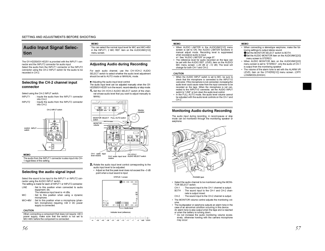
1.Set the
|
|
| Monitor |
|
|
| speaker |
MONITOR SELECT FULL AUTO switch |
|
| |
switch |
|
|
|
MONITOR |
|
|
|
volume |
|
|
|
| VF BRIGHT |
|
|
USER 1 | USER 2 USER 3 |
|
|
ND FILTER | LCD BRIGHT |
| |
| CAM/VTR | ||
2 | - | + |
|
1 |
|
|
|
| MENU |
|
|
| AUDIO SELECT | TC | |
| DISPLAY GENE. | ||
|
|
| TC |
|
|
| UB |
| STATUS |
|
|
POWER | REC |
|
|
| ||
level volume | AUDIO SELECT switch | |
| volume |
|
2.Rotate the audio input level control corresponding to the audio input level to be adjusted.
•Adjust so that the peak level does not exceed the
MEMO
•When AUDIO LIMITER in the AUDIO/MIC[1/2] menu screen is set to ON, the AUDIO LIMITER functions in manual adjust mode. Recording level is suppressed when excessive audio is input.
X See “AUDIO LIMITER” on page 87.
•The reference level for audio recorded on the tape can be set with the AUDIO REF. LEVEL item on the AUDIO/ MIC menu screen.
CAUTION
•When the AUDIO INPUT switch is set to MIC, be sure to check that the microphone is connected to the INPUT1/2 connector. If the microphone is not connected, increasing the audio level could cause noise from the input connector to be recorded on the tape. When the microphone is not con- nected to the INPUT1/2 connector, set the AUDIO INPUT switch to “LINE” or turn down the audio level control.
•In the FULL AUTO mode, the audio level volume cannot be adjusted with the audio level controls on the
Monitoring Audio during Recording
The audio input during recording, in
MEMO
•When connecting a stereotype earphone, make the fol- lowing settings to output stereo sound.
1Set the MONITOR SELECT switch to BOTH.
2Set the AUDIO MONITOR item on the AUDIO/MIC[2/2] menu screen to STEREO.
•When AUDIO MONITOR item on the AUDIO/MIC[2/2] menu screen is set to “STEREO”, only the audio of
•The volume of the alarm tone is set with the ALARM VR LEVEL item on the OTHERS[1/2] menu screen. (OFF/
LOW/MIDDLE/HIGH)
Select the sound to be input to the INPUT1 or INPUT2 con- nector using the AUDIO INPUT switch.
The setting is made for each of INPUT1 or INPUT2 connector.
LINE | : Set to this position when connected to audio |
| equipment, etc. |
| The reference input level is +4 dBs. |
MIC | : Set to this position when using a dynamic |
| microphone. |
MIC+48V : Set to this position when a microphone (phan- tom microphone) requiring +48 V DC power supply is connected.
STATUS 1 screen
![]() Audio level
Audio level
PHONES jack
•Select the audio channel to be monitored using the MONI- TOR SELECT switch.
BOTH : The sound input to the
• | The MONITOR volume control adjusts the monitoring vol- |
| ume. |
• | The loudspeaker or earphone outputs an alarm tone in the |
| case of an abnormal condition occurring in this device. |
CAUTION
When connecting a component that does not require +48 V power supply, make sure that the switch is not set to MIC+48V before the component is connected.
Indicator level (reference)
An alarm tone is also output when the tape end is reached |
or when the battery is running down. |
* Do not increase the audio monitoring volume exces- |
sively; otherwise howling with the camera microphone |
may occur. |
56 | 57 |