CONTROLS, INDICATORS AND CONNECTORS
Indications on the LCD Monitor and in the View- finder
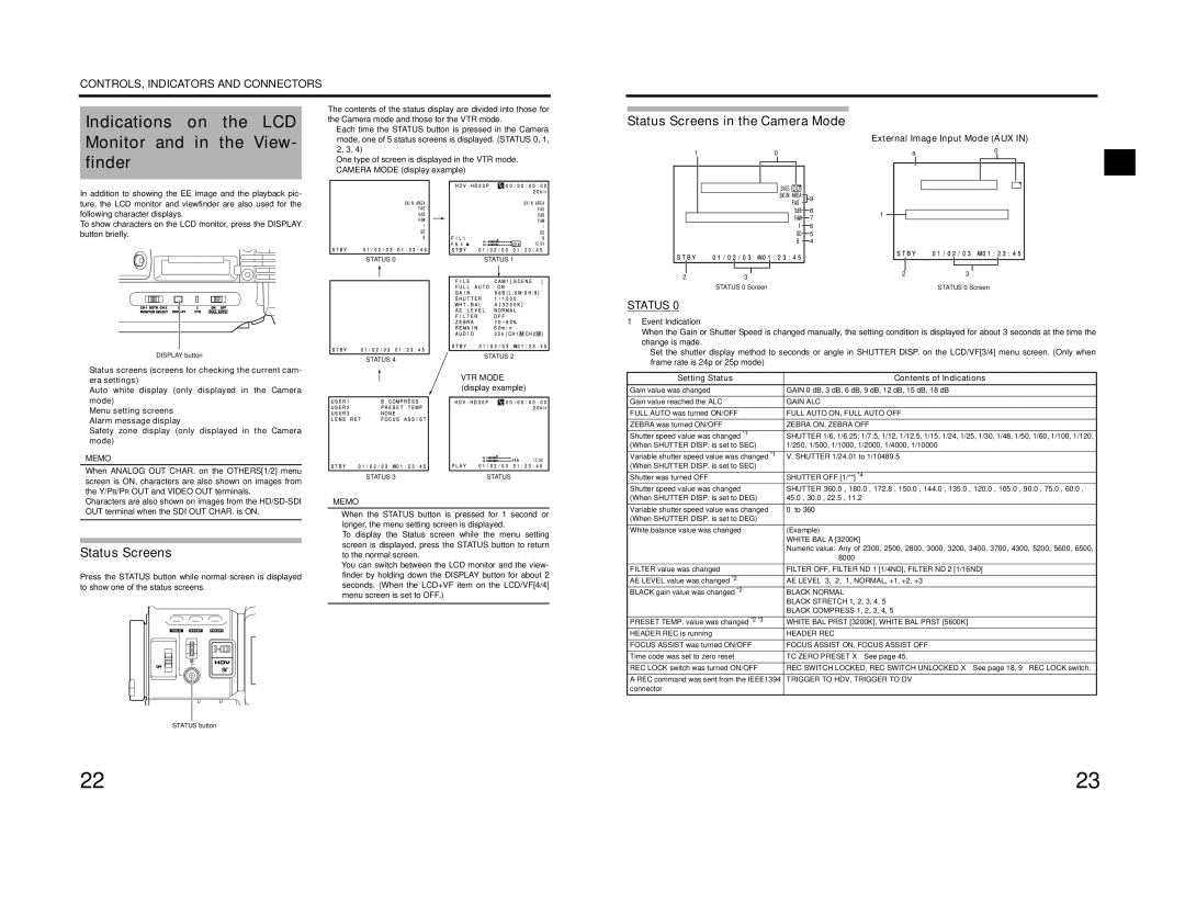
In addition to showing the EE image and the playback pic- ture, the LCD monitor and viewfinder are also used for the following character displays.
To show characters on the LCD monitor, press the DISPLAY button briefly.
The contents of the status display are divided into those for the Camera mode and those for the VTR mode.
•Each time the STATUS button is pressed in the Camera mode, one of 5 status screens is displayed. (STATUS 0, 1, 2, 3, 4)
•One type of screen is displayed in the VTR mode.
•CAMERA MODE (display example)
Status Screens in the Camera Mode
1 | 0 |
|
| 266S | DD |
|
| 9 |
|
| 8 |
|
| 7 |
|
| 6 |
|
| 5 |
|
| 4 |
External Image Input Mode (AUX IN)
a | 0 |
|
|
| |
D V - 6 0 I A U X |
|
|
| 266S | DD |
1 |
|
|
STATUS 0 | STATUS 1 |
2 | 3 |
STATUS 0 Screen
2 | 3 |
STATUS 0 Screen
DISPLAY button
Status screens (screens for checking the current cam- era settings)
Auto white display (only displayed in the Camera mode)
Menu setting screens
Alarm message display
Safety zone display (only displayed in the Camera mode)
MEMO
When ANALOG OUT CHAR. on the OTHERS[1/2] menu screen is ON, characters are also shown on images from the Y/PB/PR OUT and VIDEO OUT terminals.
Characters are also shown on images from the
Status Screens
Press the STATUS button while normal screen is displayed to show one of the status screens.
USER 1 | USER 2 | USER 3 |
SHUTTER
ND FILTER
2
1
MENU
STATUS 4 | STATUS 2 |
|
• VTR MODE (display example)
STATUS 3 | STATUS |
MEMO
•When the STATUS button is pressed for 1 second or longer, the menu setting screen is displayed.
To display the Status screen while the menu setting screen is displayed, press the STATUS button to return to the normal screen.
•You can switch between the LCD monitor and the view- finder by holding down the DISPLAY button for about 2 seconds. (When the LCD+VF item on the LCD/VF[4/4] menu screen is set to OFF.)
STATUS 0
1Event Indication
When the Gain or Shutter Speed is changed manually, the setting condition is displayed for about 3 seconds at the time the change is made.
•Set the shutter display method to seconds or angle in SHUTTER DISP. on the LCD/VF[3/4] menu screen. (Only when frame rate is 24p or 25p mode)
Setting Status | Contents of Indications |
Gain value was changed | GAIN 0 dB, 3 dB, 6 dB, 9 dB, 12 dB, 15 dB, 18 dB |
Gain value reached the ALC | GAIN ALC |
FULL AUTO was turned ON/OFF | FULL AUTO ON, FULL AUTO OFF |
ZEBRA was turned ON/OFF | ZEBRA ON, ZEBRA OFF |
Shutter speed value was changed *1 | SHUTTER 1/6, 1/6.25, 1/7.5, 1/12, 1/12.5, 1/15, 1/24, 1/25, 1/30, 1/48, 1/50, 1/60, 1/100, 1/120, |
(When SHUTTER DISP. is set to SEC) | 1/250, 1/500, 1/1000, 1/2000, 1/4000, 1/10000 |
Variable shutter speed value was changed *1 | V. SHUTTER 1/24.01 to 1/10489.5 |
(When SHUTTER DISP. is set to SEC) |
|
Shutter was turned OFF | SHUTTER OFF [1/**] *4 |
Shutter speed value was changed | SHUTTER 360.0°, 180.0°, 172.8°, 150.0°, 144.0°, 135.0°, 120.0°, 105.0°, 90.0°, 75.0°, 60.0°, |
(When SHUTTER DISP. is set to DEG) | 45.0°, 30.0°, 22.5°, 11.2° |
Variable shutter speed value was changed | 0° to 360° |
(When SHUTTER DISP. is set to DEG) |
|
White balance value was changed | (Example) |
| WHITE BAL A [3200K] |
| Numeric value: Any of 2300, 2500, 2800, 3000, 3200, 3400, 3700, 4300, 5200, 5600, 6500, |
| 8000 |
FILTER value was changed | FILTER OFF, FILTER ND 1 [1/4ND], FILTER ND 2 [1/16ND] |
AE LEVEL value was changed *2 | AE LEVEL |
BLACK gain value was changed *2 | BLACK NORMAL |
| BLACK STRETCH 1, 2, 3, 4, 5 |
| BLACK COMPRESS 1, 2, 3, 4, 5 |
PRESET TEMP. value was changed *2 *3 | WHITE BAL PRST [3200K], WHITE BAL PRST [5600K] |
HEADER REC is running | HEADER REC |
FOCUS ASSIST was turned ON/OFF | FOCUS ASSIST ON, FOCUS ASSIST OFF |
Time code was set to zero reset | TC ZERO PRESET X See page 45. |
REC LOCK switch was turned ON/OFF | REC SWITCH LOCKED, REC SWITCH UNLOCKED X See page 18, 9 REC LOCK switch. |
A REC command was sent from the IEEE1394 | TRIGGER TO HDV, TRIGGER TO DV |
STATUS
STATUS button
connector |
22 | 23 |
