6


 QU
QU
 ICK
ICK
 SET
SET U
U
 P
P
 GUIDE
GUIDE (cont.)


STEP
2
INSTALLATION
CONNECT VIDEO RECORDER TO TV
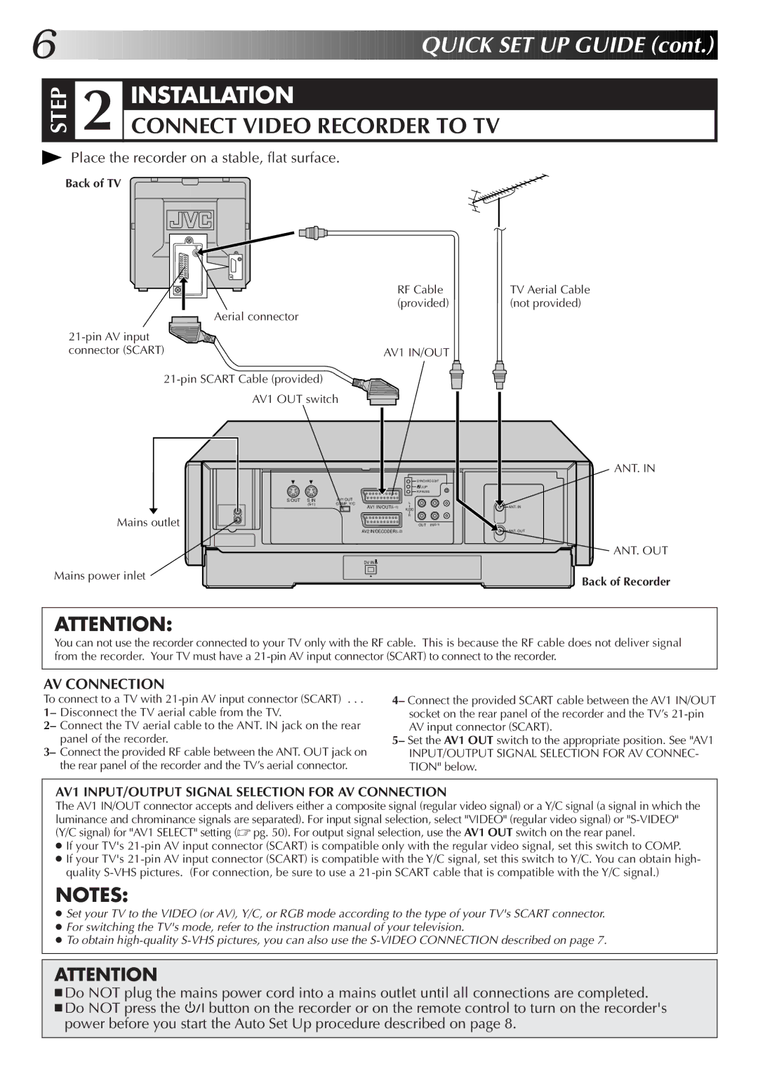
Place the recorder on a stable, flat surface.
Back of TV
| RF Cable |
Aerial connector | (provided) |
| |
| |
connector (SCART) | AV1 IN/OUT |
| |
AV1 OUT switch |
|
SYNCHRO EDIT
![]() JLIP
JLIP
R.PAUSE
S OUT S IN | AV1 OUT | L |
COMP. Y/C | ||
|
| AV1 |
|
| AUDIO |
Mains outlet |
| R |
| OUT |
AV2
DV IN ![]()
![]()
Mains power inlet
TV Aerial Cable (not provided)
ANT. IN
ANT. IN
ANT. OUT
ANT. OUT
Back of Recorder
ATTENTION:
You can not use the recorder connected to your TV only with the RF cable. This is because the RF cable does not deliver signal from the recorder. Your TV must have a
AV CONNECTION
To connect to a TV with
1– Disconnect the TV aerial cable from the TV.
2– Connect the TV aerial cable to the ANT. IN jack on the rear panel of the recorder.
3– Connect the provided RF cable between the ANT. OUT jack on the rear panel of the recorder and the TV’s aerial connector.
4– Connect the provided SCART cable between the AV1 IN/OUT socket on the rear panel of the recorder and the TV’s
5– Set the AV1 OUT switch to the appropriate position. See "AV1
INPUT/OUTPUT SIGNAL SELECTION FOR AV CONNEC- TION" below.
AV1 INPUT/OUTPUT SIGNAL SELECTION FOR AV CONNECTION
The AV1 IN/OUT connector accepts and delivers either a composite signal (regular video signal) or a Y/C signal (a signal in which the luminance and chrominance signals are separated). For input signal selection, select "VIDEO" (regular video signal) or
●If your TV's
●If your TV's
NOTES:
●Set your TV to the VIDEO (or AV), Y/C, or RGB mode according to the type of your TV's SCART connector.
●For switching the TV's mode, refer to the instruction manual of your television.
●To obtain
ATTENTION
■Do NOT plug the mains power cord into a mains outlet until all connections are completed.
■Do NOT press the ![]()
![]()
![]() button on the recorder or on the remote control to turn on the recorder's power before you start the Auto Set Up procedure described on page 8.
button on the recorder or on the remote control to turn on the recorder's power before you start the Auto Set Up procedure described on page 8.