18 | INSTALLING YOUR NEW UNIT (cont.) |
Basic Connections
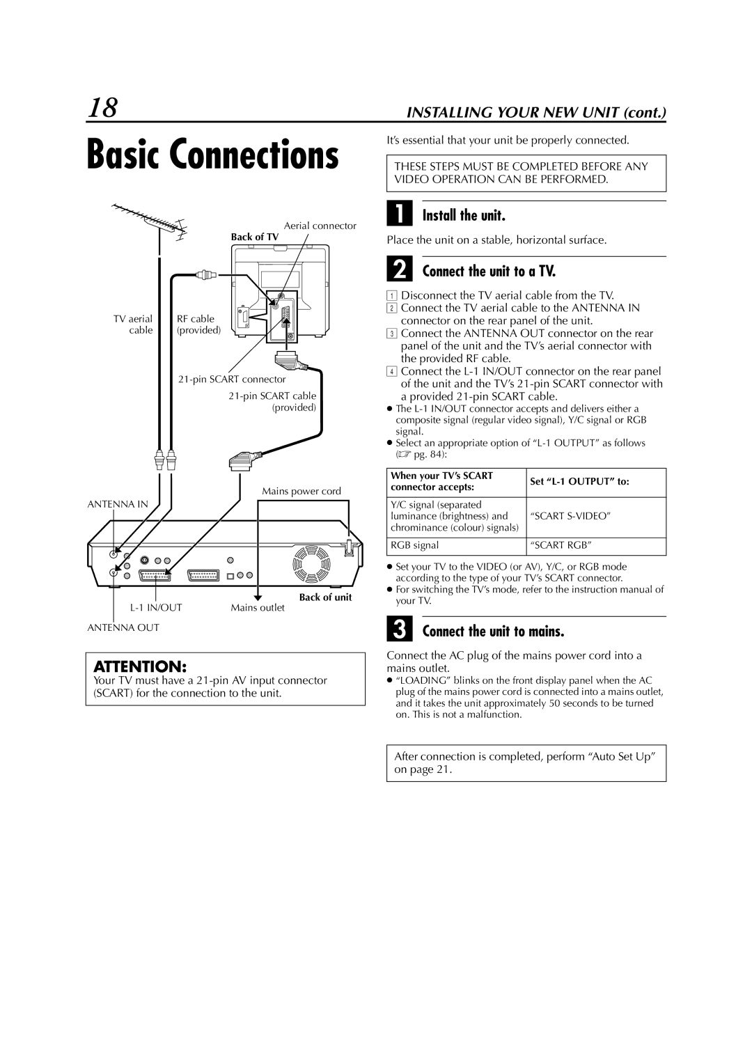
Aerial connector
Back of TV
TV aerial | RF cable |
cable | (provided) |
Mains power cord
ANTENNA IN
| Back of unit |
Mains outlet |
ANTENNA OUT
ATTENTION:
Your TV must have a
It’s essential that your unit be properly connected.
THESE STEPS MUST BE COMPLETED BEFORE ANY VIDEO OPERATION CAN BE PERFORMED.
A Install the unit.
Place the unit on a stable, horizontal surface.
B Connect the unit to a TV.
ADisconnect the TV aerial cable from the TV.
BConnect the TV aerial cable to the ANTENNA IN connector on the rear panel of the unit.
CConnect the ANTENNA OUT connector on the rear panel of the unit and the TV’s aerial connector with the provided RF cable.
DConnect the
a provided 21-pin SCART cable.
●The
●Select an appropriate option of
When your TV’s SCART | Set | |
connector accepts: | ||
| ||
|
| |
Y/C signal (separated |
| |
luminance (brightness) and | “SCART | |
chrominance (colour) signals) |
| |
|
| |
RGB signal | “SCART RGB” | |
|
|
●Set your TV to the VIDEO (or AV), Y/C, or RGB mode according to the type of your TV’s SCART connector.
●For switching the TV’s mode, refer to the instruction manual of your TV.
C Connect the unit to mains.
Connect the AC plug of the mains power cord into a mains outlet.
●“LOADING” blinks on the front display panel when the AC plug of the mains power cord is connected into a mains outlet, and it takes the unit approximately 50 seconds to be turned on. This is not a malfunction.
After connection is completed, perform “Auto Set Up” on page 21.