RX-9000VBK
For the main unit
Table of Contents
Introduction
Features
Precautions
Parts Identification
Remote Control Front Panel
Getting Started
Before Installation
Checking the Supplied Accessories
Connecting the FM and AM Antennas
AM Antenna Connections
Connecting the Speakers
Basic connecting procedure
Connecting the front speakers
Analog connections
Connecting Audio/Video Components
Connecting the rear and center speakers
Connecting the subwoofer speaker
Video component connections
Cassette deck or MD recorder
CD recorder
DVD player
Video camera
TV and/or DBS tuner
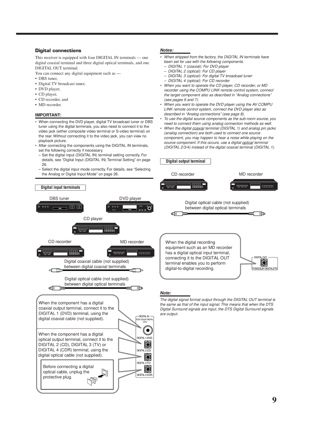
Digital output terminal
Digital connections
Digital input terminals
DBS tuner DVD player
Insert the RF rod antenna to the RF Remote Antenna terminal
Find the place where you attach the IR signal transmitter
To set up the RF rod antenna
To set up the IR signal transmitter
Replace the cover
Putting Batteries in the Remote Control
Connecting the Power Cord
Plug the power cord into an AC outlet
Merits
Multi-room Operations
Required Speaker Connections for the Sub-room
Connection Connection ı
Select and play a source
Basic Operating Procedure for Main Room
Press Power
Press Audio Power on
Set the multi-room operation selector to SUB Room
Basic Operating Procedure for Sub-Room
Green
Sub-room
Main Room Basic Operations
Turning the Power On and Off Standby
Canceling the Main Room Operations
Selecting the Main Room Source to Play
Signal and speaker indicators on the display
When digital input is selected Lights up when the left
When analog input is selected Always lights up
Selecting different sources for picture and sound
Adjusting the Main Room Volume
Activating the Main Room Front Speakers
Etc
Reinforcing the Bass
Attenuating the Input Signal
Adjusting the Subwoofer Output Level
Muting the Main Room Sound
Recording a Source
Adjusting the Front Speaker Output Balance
Using the Sleep Timer
Changing the Display Brightness
For the sub-room operations
Sub-Room Operations
Press SUB Room Control
Press SUB Room ON/OFF
Selected source name for sub-room appears
Canceling the Sub-room Operations
Selecting the Sub-room Source to Play
To use this receiver for the sub-room operations again
Press Muting to mute the sound through
Adjusting the Sub-room Volume Muting the Sub-room Sound
Operating the Playback Source for Sub-room
Activating the Sub-room Front Speakers
Changing the Source Name
Basic Settings
Setting the Front Speakers Either for Main Room or Sub-room
Setting the Subwoofer Information
Rear Delay appears on Display
Setting the Speakers for the DSP Modes
Press Setting repeatedly until
Frequency appears on the display
Delay time of the rear speaker
Turn Multi JOG to select
Output
OPT. DIG. in appears on Display
Digital Input Digital in Terminal Setting
Settings
Selecting the Analog or Digital Input Mode
Showing the Text Information on Display
Memo
Storing the Basic Settings Adjustments One Touch Operation
Adjust the sound using the functions listed above
Press ONE Touch OPERATION. Onetouchoperation
Press TUNER/SEA Memory
Using Preset Tuning
Tuning in Stations Manually
Receiving Radio Broadcasts
Selecting the FM Reception Mode
Assigning Names to Preset Stations
Creating Your Own SEA Mode
Using the SEA Modes
Selecting Your Favorite SEA Mode
Surround modes
Using the DSP Modes
What are the DSP Modes?
3D-PHONIC modes
DVD Multi Playback Mode
Reproducing the Sound Field
DAP modes
To activate the Surround
By pressing DSP Mode By pressing Surround Mode
Available DSP Modes According to the Speaker Arrangement
Speaker arrangements Available DSP modes
Adjusting the Surround Modes
Large Theater or DIG L
Adjust the rear tone
Adjust the center tone
Theater appears on Display Adjust the speaker output levels
Press Surround Mode
Adjust the room size sense
Adjust the liveness
Adjust the overall level of the effects
HALL, or Concert Arena Appears on the display
Adjusting the DAP Modes
Press DSP Mode repeatedly until
DAP mode Live Club
Concert HALL, or Concert Arena appears on the display
Repeatedly until the DAP mode
Select and play a sound source
Mode you want appears on Display
Activating the DSP Modes
Multi appears on the display
Using the DVD Multi Playback Mode
Activating the DVD Multi Playback Mode
Press DVD Multi so that DVD
Press %/ Þto move to Visual
Using the On-Screen Menus
When you finish, press Exit
Press Menu
Press %/ Þto move
Press %/ Þto move to Sound CONTROL, then press @/ #
For Dolby Digital and DTS Digital Surround
Adjusting the DVD Multi Playback Mode
Press %/ Þto move To Surround LEVEL, then press @/ #
For Dolby Pro Logic
Press %/ Þto move to SEA, then press @ / #
Press %/ Þ/ @/ #to adjust the SEA mode as you want
Press SET to store the setting into the SEA
Press %/ Þto move To SETTING, then press @/ #
Press %/ Þto move to Tuner CONTROL, then press @/ #
Press %/ Þto move To Preset Name Then press SET
Press %/ Þto move To Preset MEMORY, then press @/ #
Preset station number
Automatic Source Selection
Compu Link Remote Control System
Remote Control through the Remote Sensor on the Receiver
CD player CD recorder Cassette deck MD recorder
Synchronized Recording
Same time
Disc Search Only for CD Player
Text Compu Link Remote Control System
CD player MD recorder
Displaying the Disc Information on the TV screen
To exit from the Disc information screen
Press Text Display while CD or MD is selected as the source
Disc Information screen
Showing the Disc Information on the TV Screen
Press SET again
Press Text Display while CD is selected as the source
Press %/ Þto move To SEARCH, then Press SET
Press %/ Þto move To Performer Then press SET
Entering the Disc Information
Press %/ Þto move to Search Then press SET
Press %/ Þto move To GENRE, then Press SET
Press %/ Þto move To Title INPUT, then press SET
For the MD recorder
Press %/ Þto move to the genre you want, then press SET
Press Text Display while MD is selected as the source
Press %/ Þto move to Title Input Then press SET
If the AV Compu Link terminal on the TV is AV Compu Link EX
AV Compu Link Remote Control System
Target video components
If the AV Compu Link terminal on the TV is RECEIVER/AMP
One-Touch Video Play
CASE1 If the components are equipped with the S-video
Terminals Video terminals
One-Touch DVD Play
Automatic Power On/Off Standby
Automatic Power On
CD player
Operating JVC’s Audio/Video Components
Tuner
Sound control section Amplifier
Cassette deck
CD player-changer
CD recorder
Turntable
Operations, these buttons can be
VCR 1 VCR connected to VCR 1 jacks
DVD player
Multi only for the main room
Operating Other Manufacturers’ Video Equipment
Release TV/CATV/DBS Power
Set the remote control mode to CATV/DBS
If there are more than one code listed for your brand of TV
If there are more than one code listed for your brand
Try to operate your VCR by pressing VCR 1 Power
Release VCR 1 Power
Panasonic Primestar
28, 29, 60
11, 44
Echostar Expressvu General Instrument Hitachi
Problem Possible Cause Solution
Troubleshooting
Connect an Ntsc TV
AM tuner
Specifications
Amplifier
FM tuner IHF
1099
781 954 650
Valley Road Wayne, NJ
Limited Warranty AUDIO-2
0200HIMMDWJEIN