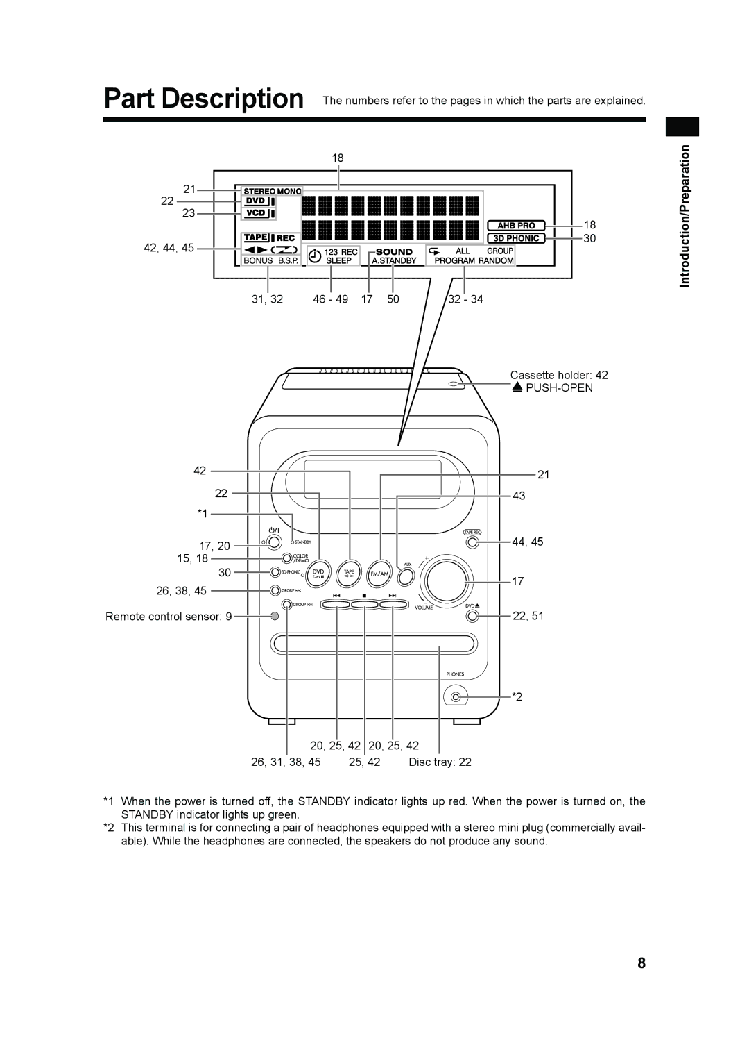
Part Description The numbers refer to the pages in which the parts are explained.
| 18 |
| Introduction/Preparation |
|
|
| |
21 |
|
|
|
22 |
|
|
|
23 |
| 18 |
|
|
|
| |
42, 44, 45 |
| 30 |
|
|
|
|
31, 32 | 46 - 49 17 50 | 32 - 34 |
Cassette holder: 42
![]()
![]()
42 |
22 |
*1 |
17, 20 |
15, 18 |
30 |
26, 38, 45 |
21
43
44, 45
17
Remote control sensor: 9 ![]()
20, 25, 42 20, 25, 42
22, 51
*2
26, 31, 38, 45 | 25, 42 | Disc tray: 22 |
*1 When the power is turned off, the STANDBY indicator lights up red. When the power is turned on, the STANDBY indicator lights up green.
*2 This terminal is for connecting a pair of headphones equipped with a stereo mini plug (commercially avail- able). While the headphones are connected, the speakers do not produce any sound.
8
