Control Elements, Displays and Connections
This section contains a brief description of all the control elements, displays and connections. The key symbols presented here are also used when describing operating sequences.
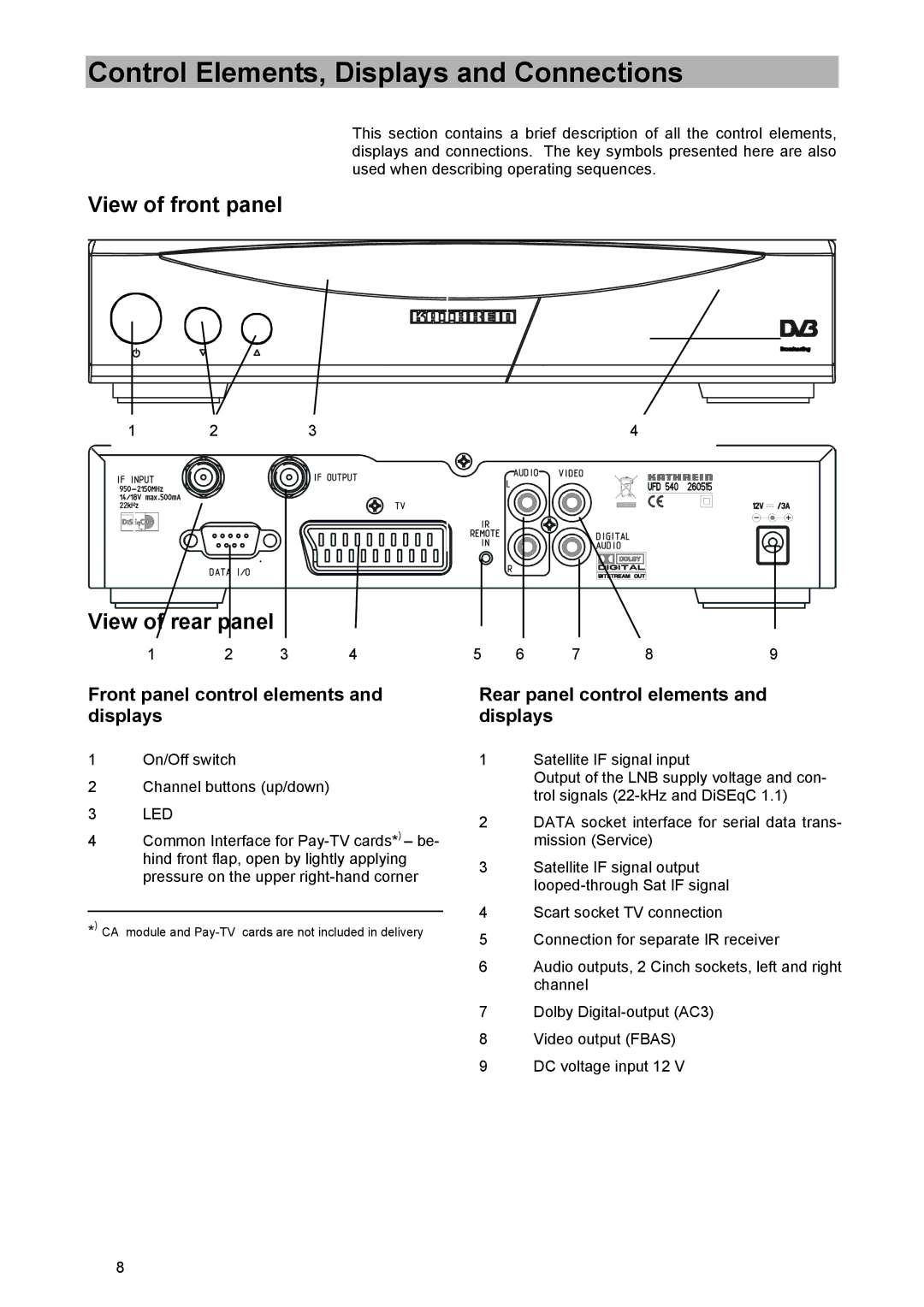
View of front panel
1 | 2 | 3 | 4 |
View of rear panel
1 | 2 | 3 | 4 | 5 | 6 | 7 | 8 | 9 |
Front panel control elements and displays
1On/Off switch
2Channel buttons (up/down)
3LED
4Common Interface for
_________________________________________
*) CA module and
Rear panel control elements and displays
1Satellite IF signal input
Output of the LNB supply voltage and con- trol signals
2DATA socket interface for serial data trans- mission (Service)
3Satellite IF signal output
4Scart socket TV connection
5Connection for separate IR receiver
6Audio outputs, 2 Cinch sockets, left and right channel
7Dolby
8Video output (FBAS)
9DC voltage input 12 V
8