MDX-G3
Factory fitted moulded mains plug
Before applying power
Safety precautions
Marking of products using lasers Except for some areas
Contents
Unpacking
Loading batteries in the remote control unit
System connection
On next page \
Connecting the accessories
FM rod antenna
AUX auxiliary component
Connecting other components
Headphones
System connection
Press the SET key
Press the Power key to turn power on
J U S T
Hour
Press the Menu key
Presetting stations automatically
EX. Bass T U N E R
EX. Bass a U T O P R E S E T
Press the AUTO/MANU key so that Auto is lit
Presetting stations manually
Preset number
EX. Bass M E M O R Y
10 EN
Press the Power key to turn power on Insert a CD
Playback of CD
Press the CD 6key
To take out the CD
Operation of keys
11 EN
Press the MD 6key
Press the Power key to turn power on Insert an MD
Playback of MD
÷ N O T I T L E ÷
To take out the MD
MD play mode indicators
A C K
13 EN
Press the Tape `key
Press the Power key to turn power on Load a tape
Playback of Tape
A Y
Playing a Dolby-encoded tape Tape EQ
Setting the reverse mode of tape Tape RVS
15 EN
To take out the Tape
16 EN
Receiving broadcast stations
17 EN
Receiving non-preset broadcast stations
To tune a radio station using numeric keys
18 EN
Press the Power key to turn power on Press the AUX key
Playing audio input from AUX component
Play the component connected to the AUX input jacks
19 EN
20 EN
Recording CD onto MD MD O.T.E
Insert a recordable MD
21 EN
4 0
Recording the CD track being played Single-track recording
Press the MD O.T.E. key on the remote
22 EN
Recording CD onto Tape Tape O.T.E
Front
Press the Tape O.T.E. key on the remote
EX. Bass T a P E S T O P
EX. Bass R E V E R S E
23 EN
Recording CD onto Tape
24 EN
25 EN
Viewing the text data CD-TEXT
Displayed information
Viewing the CD information
26 EN
To view the disc title or track titles
Viewing the MD information
EX. Bass 0 0 3 R 9 0
27 EN
EX. Bass L O U D N E S S O N
Adjusting the tone
Fine adjustment of bass and tre- ble Tone
EX. Bass E X . B a S S O N
EX. Bass a U X I N P U T ?
Adjusting the AUX input level
Press the Mute key to switch muting on or off
Muting the audio tempo- rarily Mute
30 EN
Playing CD or MD tracks in the desired sequence PGM
CD Press the CD 6 key MD Press the MD 6 key
Press the Random key so that Random is lit
Repeating a CD or MD Repeat
Playing a CD or MD in a random Random
EX. Bass ÷ N O T I T L E ÷
32 EN
Stereo LP modes
Types of recording modes
33 EN
EX. Bass M D R E C M O D E
EX. Bass L P S T a M P o n
High is displayed, then press the SET key
EX. Bass R E C S P E E D ?
EX. Bass C D ≥ M D H I G H
Make preparation for recording
35 EN
EX. Bass W a i t 7 4 m i n
Press the MD REC key
Recording onto MD
EX. Bass 0 0 1 R 7 4 0
Tips for recording CD onto MD
37 EN
Regard to track numbers at the time of recording
Start playing the source to be re- corded
Recording onto Tape
Tip for recording CD or MD onto tape
Select the source to be recorded
39 EN
Recording CD tracks onto MD or Tape in desired se- quence
Program the CD tracks in the de- sired sequence
Start recording
40 EN
Program the MD tracks in the de- sired sequence
Replace the CD and press the Best Hits key
EX. Bass 0 0 3 R 7 2 0 1 Best Hits
Press the CD 6key Press the 7STOP key
Press the Best Hits key
42 EN
Editing the MD titles
EX. Bass ÷ ÷ ÷ ÷ ÷ ÷ ÷ ÷ ÷ ÷
≤ a a
Deleting a title
Character input using the 4 and ¢keys
≤ a B C D
Changing a title
44 EN
Registering titles
Input the title
After composing the title, press the Enter key
45 EN
To cancel title copy in the middle
Copying titles
≤ W J
46 EN
Title editing character list
SET key
To cancel the Move operation in the mid- dle
Moving one track
EX. Bass 0 0 6 / 1 /0 0
EX. Bass 0 3 3 / 9 / 03
Moving several tracks at a time
EX. Bass Q . M O V E
EX. Bass 0 0 2 T I TL E
EX. Bass 0 0 4 + 0 0
To cancel the Combine operation in the middle
Combining tracks
EX. Bass C O MB I NE ?
Press the SET key again
Dividing a track
EX. Bass D I V I D E
EX. Bass P R E V 0 s +
51 EN
To cancel the Erase operation in the mid- dle
Erasing a track
Erased, and press the SET key
To cancel the Q. Erase operation in the middle
Erasing several tracks at a time
EX. Bass Q . E R a S E ?
53 EN
Canceling editing
To cancel the Cancel operation in the mid- dle
EX. Bass C a NC E L
54 EN
EX. Bass T I M E R S E T ?
EX. Bass O . T . T . S E T ?
To check or change the timer setting
Standby mode
To cancel O.T.T. timer
To re-execute O.T.T. timer with the same setting as before
T I M E
Program timer PROG.1, PROG.2
Timer playback using program timer
EX. Bass P R O G S E T ?
57 EN
Key
Timer recording using program timer
Perform steps 2 to 6 of Timer playback using program timer
R E C
59 EN
Press the Timer key on the re
To cancel program timer
60 EN
Sleep timer Sleep
To check the remaining sleep timer
To cancel sleep timer
61 EN
Disc handling precautions
Important items
N O D I S C
62 EN
Handling of MD
63 EN
Maintenance
64 EN
Maintenance of the unit
Regard to contact cleaner
Memory backup function
Common section
Operation to reset
Case of difficulty
65 EN
MD recorder section
Case of difficulty Remote control unit
MD recorder section Symptoms related to the MD standard
66 EN
Cassette deck section
67 EN
CD player section
68 EN
Display message list
Scms
69 EN
70 EN
Specifications
71 EN
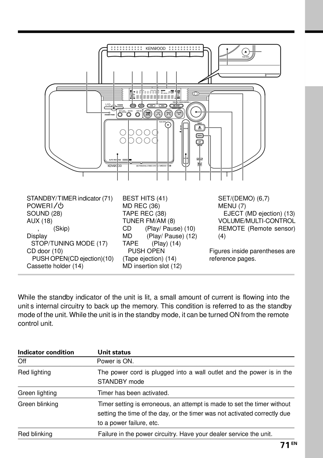
Controls and indicators
Main Unit
For your records
Remote control unit