1 INSTALLATION
FIXED STATION INSTALLATION
When you use the transceiver at a fixed location, the transceiver requires 13.8 V DC power supply (The
REMOTE CONTROL PANEL INSTALLATION
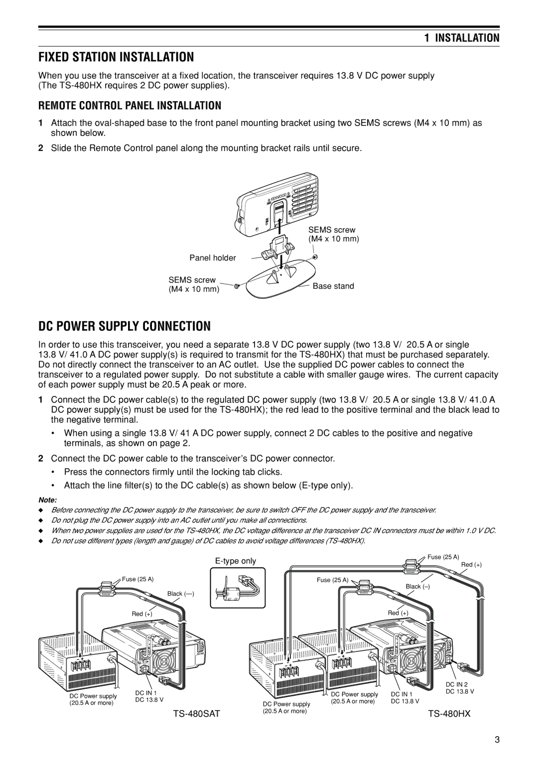
1Attach the
2Slide the Remote Control panel along the mounting bracket rails until secure.
| SEMS screw | |
| (M4 x 10 mm) | |
Panel holder |
| |
SEMS screw | Base stand | |
(M4 x 10 mm) | ||
|
DC POWER SUPPLY CONNECTION
In order to use this transceiver, you need a separate 13.8 V DC power supply (two 13.8 V/ 20.5 A or single
13.8V/ 41.0 A DC power supply(s) is required to transmit for the
1Connect the DC power cable(s) to the regulated DC power supply (two 13.8 V/ 20.5 A or single 13.8 V/ 41.0 A DC power supply(s) must be used for the
¥When using a single 13.8 V/ 41 A DC power supply, connect 2 DC cables to the positive and negative terminals, as shown on page 2.
2Connect the DC power cable to the transceiverÕs DC power connector.
¥Press the connectors firmly until the locking tab clicks.
¥Attach the line filter(s) to the DC cable(s) as shown below
Note:
◆Before connecting the DC power supply to the transceiver, be sure to switch OFF the DC power supply and the transceiver.
◆Do not plug the DC power supply into an AC outlet until you make all connections.
◆When two power supplies are used for the
◆Do not use different types (length and gauge) of DC cables to avoid voltage differences
![]() Fuse (25 A)
Fuse (25 A)
Black
Red (+)
|
| AT |
| 2 | 1 |
|
| DC 2 13.8V |
DC | 1 | GND |
13.8V |
| |
|
| Fuse (25 A) |
|
| Red (+) |
Fuse (25 A) |
| Black |
|
| |
| Red (+) | |
|
| AT |
| 2 | 1 |
|
| DC 2 13.8V |
DC | 1 | GND |
13.8V |
| |
|
|
|
|
| DC IN 2 |
DC Power supply | DC IN 1 |
| DC Power supply | DC IN 1 | DC 13.8 V |
|
| ||||
(20.5 A or more) | DC 13.8 V | DC Power supply | (20.5 A or more) | DC 13.8 V |
|
|
| ||||
|
| (20.5 A or more) |
|
| |
|
|
|
|
3