15 INSTALLING OPTIONS
¥
¥IF filters: Insert a primary IF filter in the OPTION FILTER1 location, and a secondary IF filter in the OPTION FILTER2 location. The transceiver automatically detects what optional IF filter(s) is installed when it is turned ON.
5Solder all pins on the reverse side of the PCB.
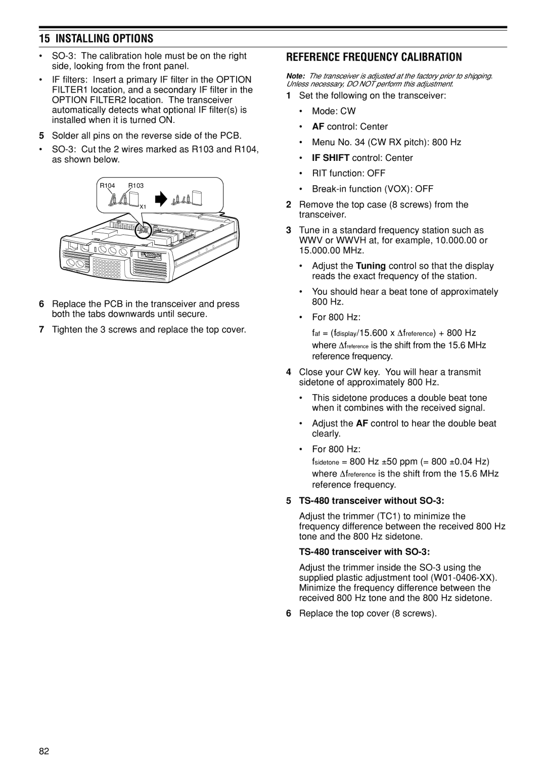
¥
R104 | R103 | |
|
| X1 |
|
| OPTION FILTER1 |
EXT.SP |
| OPTION FILTER2 |
| DATA | REMOTE |
|
| |
MIC
PANEL
COM
P |
|
ADDLE | KEY |
6Replace the PCB in the transceiver and press both the tabs downwards until secure.
7Tighten the 3 screws and replace the top cover.
REFERENCE FREQUENCY CALIBRATION
Note: The transceiver is adjusted at the factory prior to shipping. Unless necessary, DO NOT perform this adjustment.
1Set the following on the transceiver:
¥Mode: CW
¥AF control: Center
¥Menu No. 34 (CW RX pitch): 800 Hz
¥IF SHIFT control: Center
¥RIT function: OFF
¥
2Remove the top case (8 screws) from the transceiver.
3Tune in a standard frequency station such as WWV or WWVH at, for example, 10.000.00 or 15.000.00 MHz.
¥Adjust the Tuning control so that the display reads the exact frequency of the station.
¥You should hear a beat tone of approximately 800 Hz.
¥For 800 Hz:
faf = (fdisplay/15.600 x ∆freference) + 800 Hz where ∆freference is the shift from the 15.6 MHz reference frequency.
4Close your CW key. You will hear a transmit sidetone of approximately 800 Hz.
¥This sidetone produces a double beat tone when it combines with the received signal.
¥Adjust the AF control to hear the double beat clearly.
¥For 800 Hz:
fsidetone = 800 Hz ±50 ppm (= 800 ±0.04 Hz) where ∆freference is the shift from the 15.6 MHz reference frequency.
5TS-480 transceiver without SO-3:
Adjust the trimmer (TC1) to minimize the frequency difference between the received 800 Hz tone and the 800 Hz sidetone.
TS-480 transceiver with SO-3:
Adjust the trimmer inside the
6Replace the top cover (8 screws).
82