INSTALLING OPTIONS
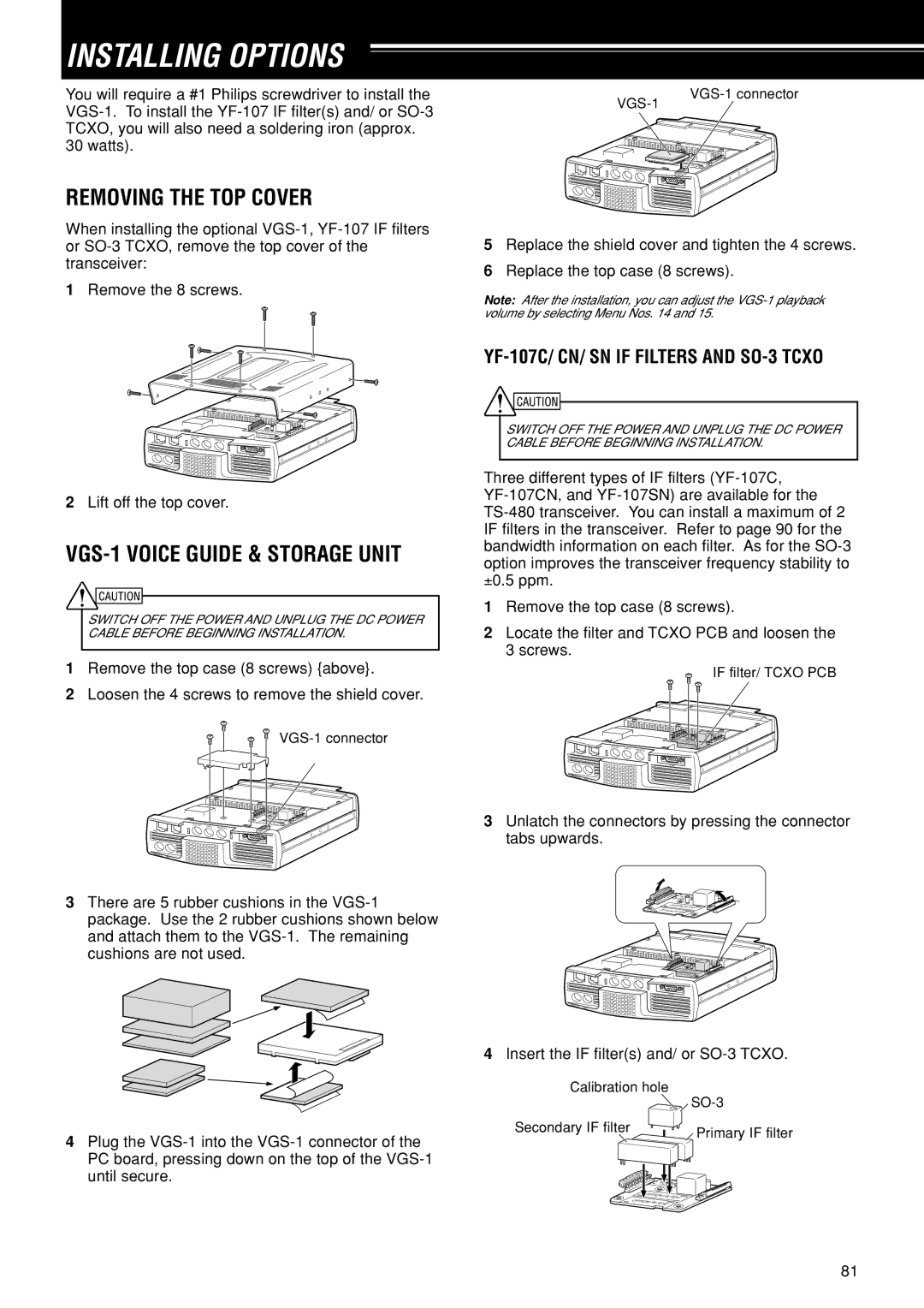
You will require a #1 Philips screwdriver to install the
30 watts).
REMOVING THE TOP COVER
When installing the optional
1Remove the 8 screws.
|
| |
| ||
| EXT.SP DATA | REMOTE |
MIC |
| |
|
| |
| PANEL |
|
|
| COM |
P |
|
|
ADDLE | KEY |
|
5Replace the shield cover and tighten the 4 screws.
6Replace the top case (8 screws).
Note: After the installation, you can adjust the
YF-107C/ CN/ SN IF FILTERS AND SO-3 TCXO
EXT.SP | DATA | REMOTE |
MIC |
| |
PANEL |
|
|
|
| COM |
P |
|
ADDLE | KEY |
2Lift off the top cover.
VGS-1 VOICE GUIDE & STORAGE UNIT
SWITCH OFF THE POWER AND UNPLUG THE DC POWER CABLE BEFORE BEGINNING INSTALLATION.
1Remove the top case (8 screws) {above}.
2Loosen the 4 screws to remove the shield cover.
EXT.SP | DATA | REMOTE |
MIC
PANEL
COM
PADDLE | KEY |
3There are 5 rubber cushions in the
4Plug the
until secure.
SWITCH OFF THE POWER AND UNPLUG THE DC POWER CABLE BEFORE BEGINNING INSTALLATION.
Three different types of IF filters
±0.5 ppm.
1Remove the top case (8 screws).
2Locate the filter and TCXO PCB and loosen the 3 screws.
IF filter/ TCXO PCB
EXT.SP | DATA | REMOTE |
MIC |
| |
PANEL |
|
|
|
| COM |
PADDLE | KEY |
3Unlatch the connectors by pressing the connector tabs upwards.
OPTION | FILTER1 | |
OPTION | FILTER2 | |
EXT.SP | DATA | REMOTE |
MIC |
| |
|
| |
PANEL |
|
|
|
| COM |
PADDLE | KEY |
|
4Insert the IF filter(s) and/ or
Calibration hole
|
|
| |
Secondary IF filter |
|
| Primary IF filter |
|
|
| |
|
| NIO | O |
|
| XO | |
OPTION | FILTER1 | ||
OPTION | FILTER2 |
| |
|
| ||
81
