14 CONNECTING PERIPHERAL EQUIPMENT
RTTY OPERATION
Use the REMOTE and DATA connectors to interface with your MCP. If your MCP supports RTTY keying output, connect the output to pin 8 of the REMOTE connector. Connect the demodulation input line of the MCP to
pin 5 of the DATA connector {page 78}. Also, connect the transmission control line of the MCP to pin 3 of the REMOTE terminal. Select “FSK” or ”FSR” when you operate the RTTY mode.
Note: Do not share a single power supply between the transceiver and the RTTY equipment. Keep as wide a separation as possible between the transceiver and the RTTY equipment to reduce
MCP
Power supply
MCP
| EXT.SP | DATA | REMOTE |
| MIC |
| |
|
|
| |
PANEL |
|
| |
|
| COM | |
| P |
|
|
| KEY |
|
|
![]()
Power supply for the
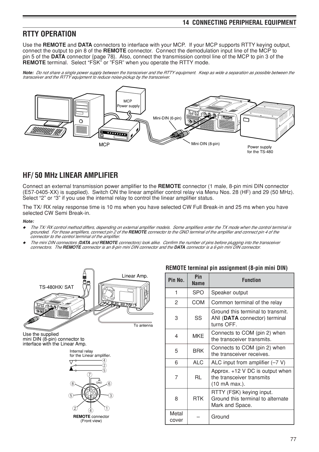
HF/ 50 MHz LINEAR AMPLIFIER
Connect an external transmission power amplifier to the REMOTE connector (1 male,
The TX/ RX relay response time is 10 ms when you have selected CW Full
Note:
◆The TX/ RX control method differs, depending on external amplifier models. Some amplifiers enter the TX mode when the control terminal is grounded. For those amplifiers, connect pin 2 of the REMOTE connector to the GND terminal of the amplifier and connect pin 4 of the connector to the control terminal of the amplifier.
◆The mini DIN connectors (DATA and REMOTE connectors) look alike. Confirm the number of pins before plugging into the transceiver connectors. The REMOTE connector is an
Linear Amp.
EXT.SP | DATA | REMOTE |
MIC |
|
|
PANEL |
|
|
|
| COM |
PADELE
To antenna
Use the supplied
mini DIN
Internal relay
for the Linear amplifier.
| r |
| w |
| t |
| u |
i | GND y |
t | e |
w r q
REMOTE connector
(Front view)
REMOTE terminal pin assignment (8-pin mini DIN)
Pin No. | Pin | Function | |
Name | |||
|
| ||
1 | SPO | Speaker output | |
|
|
| |
2 | COM | Common terminal of the relay | |
|
|
| |
|
| Ground this terminal to transmit. | |
3 | SS | ANI (DATA connector) terminal | |
|
| turns OFF. | |
|
|
| |
4 | MKE | Connects to COM (pin 2) when | |
the transceiver transmits. | |||
|
| ||
|
|
| |
5 | BRK | Connects to COM (pin 2) when | |
the transceiver receives. | |||
|
| ||
|
|
| |
6 | ALC | ALC input from amplifier | |
|
|
| |
|
| Approx. +12 V DC is output when | |
7 | RL | the transceiver transmits | |
|
| (10 mA max.). | |
|
|
| |
|
| RTTY (FSK) keying input. | |
8 | RTK | Ground this terminal to alternate | |
|
| Mark and Space. | |
|
|
| |
Metal | – | Ground | |
cover | |||
|
| ||
|
|
|
77