TURN ANGLE POTENTIOMETER INSTALLATION
SX TRANSISTOR CONTROL | Page 69 |
Section 8.0 TURN ANGLE POTENTIOMETER INSTALLATION
Section 8.1 GENERAL:
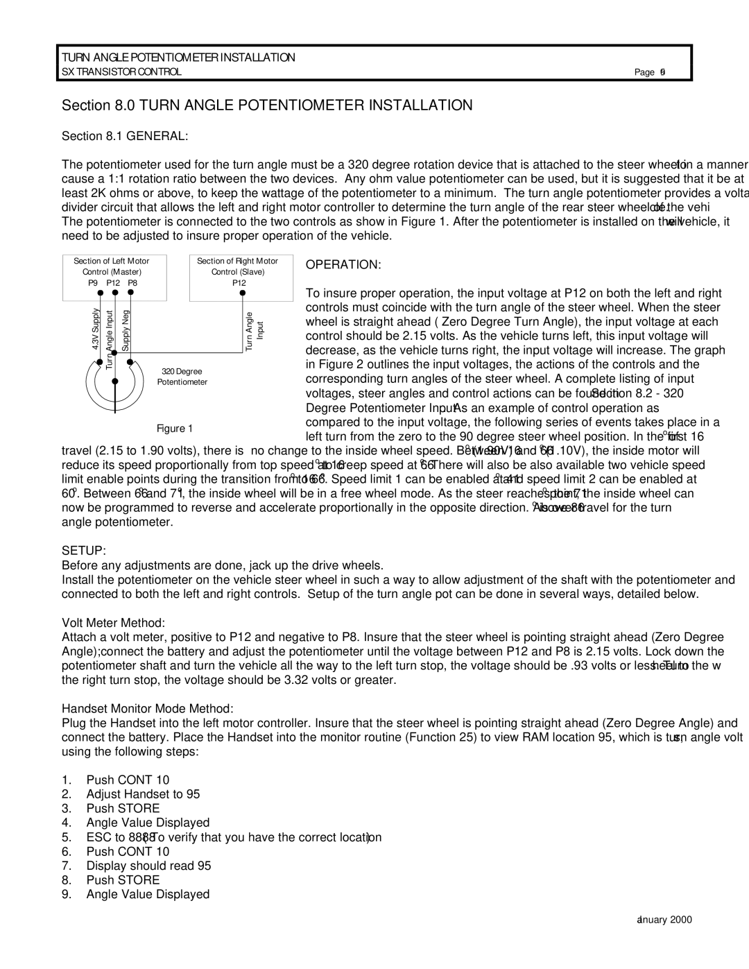
The potentiometer used for the turn angle must be a 320 degree rotation device that is attached to the steer wheel in a manner to cause a 1:1 rotation ratio between the two devices. Any ohm value potentiometer can be used, but it is suggested that it be at least 2K ohms or above, to keep the wattage of the potentiometer to a minimum. The turn angle potentiometer provides a voltage divider circuit that allows the left and right motor controller to determine the turn angle of the rear steer wheel of the vehicle. The potentiometer is connected to the two controls as show in Figure 1. After the potentiometer is installed on the vehicle, it will need to be adjusted to insure proper operation of the vehicle.
Section of Left Motor |
|
| Section of Right Motor | OPERATION: | |||||||
Control (Master) |
|
| Control (Slave) |
| |||||||
P9 P12 P8 |
|
|
| P12 | To insure proper operation, the input voltage at P12 on both the left and right | ||||||
|
|
|
|
|
|
|
|
|
|
| |
|
|
|
|
|
|
|
|
|
|
| |
4.3V Supply |
| Turn Angle Input |
|
|
|
|
|
|
|
| controls must coincide with the turn angle of the steer wheel. When the steer |
|
|
|
|
|
|
|
|
| wheel is straight ahead ( Zero Degree Turn Angle), the input voltage at each | ||
|
|
|
|
|
|
|
|
| control should be 2.15 volts. As the vehicle turns left, this input voltage will | ||
|
|
|
|
|
|
|
|
| decrease, as the vehicle turns right, the input voltage will increase. The graph | ||
| SupplyNeg |
|
|
|
|
|
| AngleTurn Input | |||
|
|
|
|
|
|
| in Figure 2 outlines the input voltages, the actions of the controls and the | ||||
|
| 320 Degree |
|
| |||||||
|
|
|
|
|
|
|
| corresponding turn angles of the steer wheel. A complete listing of input | |||
|
|
|
|
|
| Potentiometer |
|
| |||
|
|
|
|
|
|
|
| ||||
|
|
|
|
|
|
|
|
|
|
| voltages, steer angles and control actions can be found in Section 8.2 - 320 |
|
|
|
|
|
|
|
|
|
|
| Degree Potentiometer Input. As an example of control operation as |
|
|
|
|
| Figure 1 |
|
| compared to the input voltage, the following series of events takes place in a | |||
|
|
|
|
|
|
| left turn from the zero to the 90 degree steer wheel position. In the first 16 o of | ||||
travel (2.15 to 1.90 volts), there is | no change to the inside wheel speed. Between 16o (1.90V) and 66o (1.10V), the inside motor will | ||||||||||
reduce its speed proportionally from top speed at 16o to creep speed at 66o. There will also be also available two vehicle speed limit enable points during the transition from 16o to 66o. Speed limit 1 can be enabled at 41o and speed limit 2 can be enabled at 60o. Between 66o and 71o, the inside wheel will be in a free wheel mode. As the steer reaches the 71o point, the inside wheel can now be programmed to reverse and accelerate proportionally in the opposite direction. Above 86o is over travel for the turn angle potentiometer.
SETUP:
Before any adjustments are done, jack up the drive wheels.
Install the potentiometer on the vehicle steer wheel in such a way to allow adjustment of the shaft with the potentiometer and connected to both the left and right controls. Setup of the turn angle pot can be done in several ways, detailed below.
Volt Meter Method:
Attach a volt meter, positive to P12 and negative to P8. Insure that the steer wheel is pointing straight ahead (Zero Degree Angle); connect the battery and adjust the potentiometer until the voltage between P12 and P8 is 2.15 volts. Lock down the potentiometer shaft and turn the vehicle all the way to the left turn stop, the voltage should be .93 volts or less. Turn the wheel to the right turn stop, the voltage should be 3.32 volts or greater.
Handset Monitor Mode Method:
Plug the Handset into the left motor controller. Insure that the steer wheel is pointing straight ahead (Zero Degree Angle) and connect the battery. Place the Handset into the monitor routine (Function 25) to view RAM location 95, which is turn angle volts, using the following steps:
1.Push CONT 10
2.Adjust Handset to 95
3.Push STORE
4.Angle Value Displayed
5.ESC to 8888 ( To verify that you have the correct location )
6.Push CONT 10
7.Display should read 95
8.Push STORE
9.Angle Value Displayed
January 2000