INSTALLATION AND OPERATION MANUAL
IT/IP TRANSISTOR CONTROL
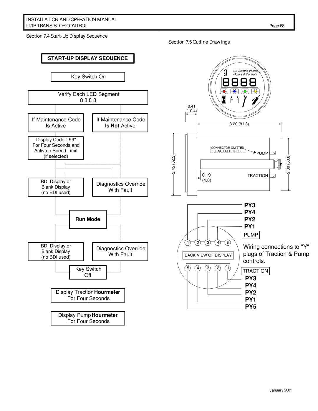
Section 7.4 Start-Up Display Sequence
START-UP DISPLAY SEQUENCE
Key Switch On
Verify Each LED Segment
Page 68
Section 7.5 Outline Drawings
g | GE Electric Vehicle |
| Motors & Controls |
8 8 8 8
0.41
(10.4)
+ -
If Maintenance Code
Is Active
Display Code
For Four Seconds and
Activate Speed Limit
(if selected)
If Maintenance Code
Is Not Active
2.45 (62.2)
3.20 (81.3)
| CONNECTOR OMITTED |
|
|
| IF NOT REQUIRED | PUMP | 2.00 (50.8) |
|
| ||
0.19 |
| TRACTION | |
|
|
BDI Display or |
| Diagnostics Override | ||
Blank Display |
| |||
| With Fault | |||
(no BDI used) |
| |||
|
| |||
|
|
|
|
|
|
|
|
|
|
Run Mode
|
|
|
|
|
BDI Display or |
| Diagnostics Override | ||
Blank Display |
| |||
| With Fault | |||
(no BDI used) |
| |||
|
| |||
Key Switch
Off
Display TractionHourmeter
For Four Seconds
Display Pump Hourmeter
For Four Seconds
(4.8) |
PY3
PY4
PY2
PY1
|
|
|
|
| PUMP |
1 | 2 | 3 | 4 | 5 | Wiring connections to "Y" |
|
|
|
|
| |
BACK VIEW OF DISPLAY | plugs of Traction & Pump | ||||
|
|
|
|
| controls. |
5 | 4 | 3 | 2 | 1 | TRACTION |
|
|
|
|
| |
|
|
|
|
| PY3 |
|
|
|
|
| PY4 |
|
|
|
|
| PY2 |
|
|
|
|
| PY1 |
|
|
|
|
| PY5 |
January 2001