Manuals
/
GE
/
Musical Instruments & Equipment
/
Musical Instrument
GE
IC3645SP4U400N3, IC3645SR4U404N2
operation manual
Outline SX-3 and SR-3 Package Size
Models:
IC3645SP4U400N3
IC3645SR4U404N2
1
12
74
74
Download
74 pages
52.3 Kb
9
10
11
12
13
14
15
16
Motor Characteristics
Install
High-Level Signals Level H
Symptom
Reset to Zero Only BDI
Diagnostic Status Codes
Setup
Discharged battery
Adjustable Features
Cleaner
Page 12
Image 12
OUTLINE DRAWINGS, ELEMENTARY DRAWINGS AND INPUTS/OUTPUTS
SX TRANSISTOR CONTROL
Page
12
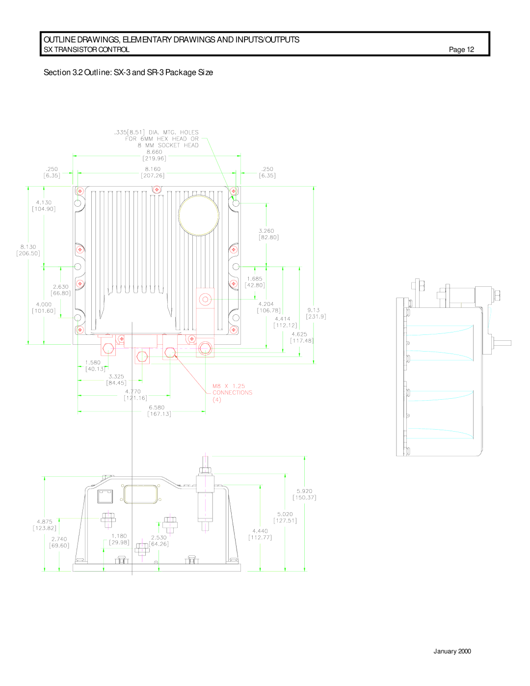
Section 3.2 Outline:
SX-3
and
SR-3
Package Size
January 2000
Page 11
Page 13
Page 12
Image 12
Page 11
Page 13
Contents
Installation and Operation
Table of Contents
20-40
41-45
46-52
57-62
Basic Operation and Features
Motor Characteristics
More Features with Fewer Components
Solid-State Reversing
Flexible System Application
Slows with the increase of current in the field
1.b Creep Speed
1.c Control Acceleration
2 Current Limit
3.c Pedal Position Plug Braking
6 Steer Pump Contactor Time Delay
4.b Speed Limits
4.c Proportional Operation for Dual Motor Vehicles
5 Ramp Operation 5a Ramp Start
Diagnostics 1 Systems Diagnostics
7 On-Board Coil Drivers & Internal Coil Suppression
System Protective Override 1 Static Return to Off SRO
2 Accelerator Volts Hold Off
3.a Maintenance Alert & Speed Limit
4 Battery Discharge Indication BDI
3 Hourmeter Readings
4.a Internal Resistance Compensation
Basic Operation and Features
Outline DRAWINGS, Elementary Drawings and INPUTS/OUTPUTS
Part Number
Argument
Outline SX-3 and SR-3 Package Size
Drawings and INPUTS/OUTPUTS
DRAWINGS, Elementary Drawings and INPUTS/OUTPUTS Control
Section
Connections to Main Plug 23 PIN and Y Plug 12 PIN
PIN
Diagnostic Status Codes
High-Level Signals Level H
Medium-Power Signals Level MP
2.d. High Power Signals Level HP
Cable Spacing Guidelines
Cleaner
Reconnect plugs
328A1777G1
General Troubleshooting Instructions
No seat switch or deadman switch
Traction Control Codes
Traction
Status Code
Reverse directional switch is closed on
Description of Status Cause of Status Indication
Start switch fails to close
Accelerator depressed with no
Direction selected
KEY Negative
Directional switches are closed at
Both the forward and reverse
Same time
Start switch closed on power up after
Initial key switch closure
Discharged battery
Motor field current is high on start up
Reverse direction
Forward direction
Volts DC Power supply is less than 10 volts
Run mode
Motor field current is too high during
Traction Controller
Slave/auxiliary control
Transistor over temperature
Open thermal protector TP or
Motor armature offset voltage is too
Low
Armature transistor did not turn off
Properly
Than 12% of battery volts
Armature transistor did not turn on
Look Ahead test for A2 volts less
Motor field current is too low during
Capacitor volts are low before the line
Contactor closes
Controller motor current sensor
Input too low during running
Line driver input P2-17 is less
Description
Armature current exceeds
Armature transistor limit
Verify connection between the master control P21
Traction Status Code
Symptom
Temperature
TMM Status Codes
Steer
Plug P5 pump is shorted to positive
Plug P8 pump is shorted to positive
Corrective Actions TROUBLE-SHOOTING Diagram YES
Symptom
Pump
Possible Cause
Transistor is over temperature
Open thermal protector TP1 or
No power to pump motor
Pump Controller motor current
Sensor input is missing
Control range
Power Transistor Q1 did not
Power Transistor Q1 did not turn on
Turn off properly
With no pump contactor, control
Capacitor volts are low after the line
Contactor closes
Controller motor current
Sensor input voltage polarity
Check
Battery voltage is less than
Voltage at capacitor 1C is less than Volts
TMM7A
3 TMM Pump Control Connections
TMM7A Outline Drawings
Adjustable Features
START-UP Display Sequence
Accessing Stored Status Codes With GE Handset
Action
Remarks
Function
Function 10 Field Current for Regen
Battery Volts
Battery volts Set units
Internal Resistance Compensation
Function 16 Stall Trip Point with % ON-TIME Push
Function 19 Maintenance Code Tens and Units Hours SET
Function 25 Monitor
Function 26 Base Ratio
Function 49 Mode 1 Field Weakening Start Push
Function 51 Mode 1 MAX Armature % on
Function 28 Stored Status Code Count Pointer Push
Function 52 Mode 2 Armature Controlled Acceleration
Function 55 Mode 2 MAX Armature % on
Function 57 Mode 3 Field Weakening Start
Function 59 Mode 3 MAX Armature % on
Summary of Current Limit Adjustments
Field Current
Function Current Limit
Function 14 not Applicable
Function 16 Speed / Torque Compensation
Speed / Torque Compensation Table Voltage Setting
Function 48 Mode 1 Controlled Acceleration Push
Function 49 Mode 1 Speed Limit 2 SL2 Push
Function 50 Mode 1 Speed Limit 3 SL3
Function 53 Mode 2 Speed Limit 2 SL2
Function 54 Mode 2 Speed Limit 3 SL3
Function 55 not Applicable
Function 59 not Applicable
Dash Displays
Application
Standard Dash Displays
Connections
Start-Up Display Sequence
Outline Drawings
Turn Angle Potentiometer Installation
Setup
Operation
Degree Potentiometer for Steer Angle Input
Degree Potentiometer Left Right
RS-232 Memory MAP Tables
Traction Control
Restrictions Function
Reset to Zero Only Stored Status Code #5
Reset to Zero Only Stored Status Code #6
Reset to Zero Only HoursTens/Ones
Reset to Zero Only HoursThou/Hun
Reset to Zero Only Stored Status Code #16
Reset to Zero Only Dash Display CA-1 Dash Display FWS-1
None Dash Display Ratio2-1
None
Top
Page
Image
Contents