ADJUSTABLE FEATURES
SX TRANSISTOR CONTROLS
vehicle manufacturer. Card type selection must be made within the capabilities of the control panel used and the supporting electro mechanical devices. Failure to comply with proper application standards could result in mis- operation or damage to the control and/or motors.
FUNCTION 18 STEER PUMP TIME DELAY ( Push CONT 3 )
This function allows for the selection of steer pump contactor pick up input, either seat switch or directional switch closing, and adjustment of the time delay for the contactor drop out.
•Pick up steer pump contactor on seat switch closure and time delay drop out of steer pump contactor on seat switch opening:
Range | 1.5 to 65 seconds |
Setting | Between 0 and 128 |
Resolution | 0.5 seconds per set unit |
Example: Setting of 20 = (20 x 0.5) + 1.5 = 11.5 seconds
•Pick up steer pump contactor on directional switch closure and time delay drop out of steer pump contactor on directional switch opening:
Range | 0.5 to 63 seconds |
Setting | Between 129 and 255 |
Resolution | 0.5 seconds per set unit |
Example: Setting of 149 =
Note: Contactor drop out will be 1.5 seconds after the seat switch opens.
FUNCTION 19 MAINTENANCE CODE TENS AND UNITS HOURS SET
( Push CONT 4 )
This function allows for the adjustment of the tens and units hours of the maintenance code activation time.
Range | 0 to 99 |
Set | 0 to 99 |
Example | 9999 Hours |
FUNCTION 20 MAINTENANCE CODE THOUSANDS AND HUNDREDS HOURS SET
( Push CONT 5 )
This function allows for the adjustment of the thousands and hundreds hours of the maintenance code activation time.
Page 60
Range | 0 to 240 |
Set | 0 to 240 |
Example | 9999 Hours |
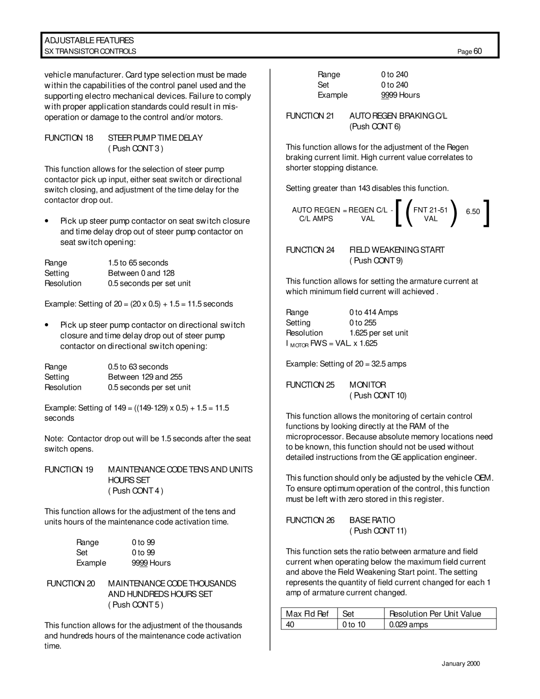
FUNCTION 21 AUTO REGEN BRAKING C/L (Push CONT 6)
This function allows for the adjustment of the Regen braking current limit. High current value correlates to shorter stopping distance.
Setting greater than 143 disables this function.
AUTO REGEN = REGEN C/L - | FNT | ( | 6.50 | [ | ||
C/L AMPS | VAL | [( | VAL |
| ||
|
|
| ||||
FUNCTION 24 FIELD WEAKENING START ( Push CONT 9)
This function allows for setting the armature current at which minimum field current will achieved .
Range | 0 to 414 Amps |
Setting | 0 to 255 |
Resolution | 1.625 per set unit |
I MOTOR FWS = VAL. x 1.625
Example: Setting of 20 = 32.5 amps
FUNCTION 25 MONITOR
( Push CONT 10)
This function allows the monitoring of certain control functions by looking directly at the RAM of the microprocessor. Because absolute memory locations need to be known, this function should not be used without detailed instructions from the GE application engineer.
This function should only be adjusted by the vehicle OEM. To ensure optimum operation of the control, this function must be left with zero stored in this register.
FUNCTION 26 BASE RATIO
( Push CONT 11)
This function sets the ratio between armature and field current when operating below the maximum field current and above the Field Weakening Start point. The setting represents the quantity of field current changed for each 1 amp of armature current changed.
Max Fld Ref | Set | Resolution Per Unit Value |
40 | 0 to 10 | 0.029 amps |
January 2000