Kenwood TS-590S manual Up Conversion, Reception, 7Dynamic Range in the 50 MHz Band

Models: TS-590S

1 76
Download 76 pages 27.47 Kb
Page 14
Image 14
1.3 Up Conversion

1 RECEPTION

1.3 Up Conversion

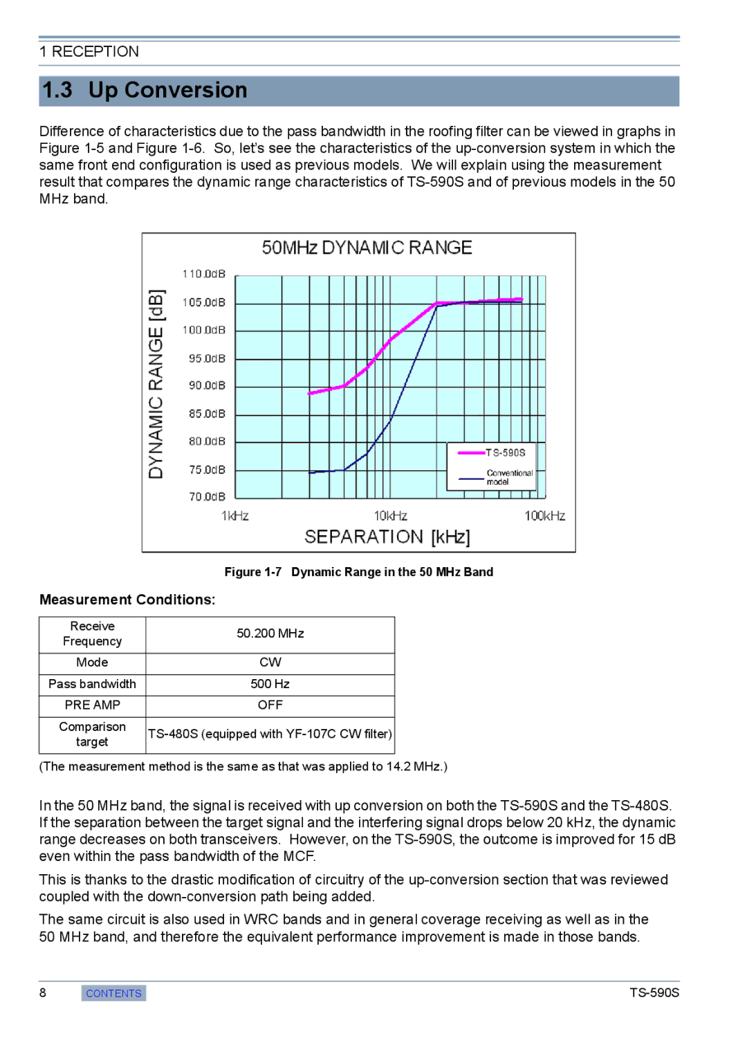
Difference of characteristics due to the pass bandwidth in the roofing filter can be viewed in graphs in Figure 1-5 and Figure 1-6. So, let’s see the characteristics of the up-conversion system in which the same front end configuration is used as previous models. We will explain using the measurement result that compares the dynamic range characteristics of TS-590S and of previous models in the 50 MHz band.

Figure 1-7 Dynamic Range in the 50 MHz Band

Measurement Conditions:

Receive

50.200 MHz

Frequency


Mode

CW


Pass bandwidth

500 Hz


PRE AMP

OFF


Comparison

TS-480S (equipped with YF-107C CW filter)

target


(The measurement method is the same as that was applied to 14.2 MHz.)

In the 50 MHz band, the signal is received with up conversion on both the TS-590S and the TS-480S. If the separation between the target signal and the interfering signal drops below 20 kHz, the dynamic range decreases on both transceivers. However, on the TS-590S, the outcome is improved for 15 dB even within the pass bandwidth of the MCF.

This is thanks to the drastic modification of circuitry of the up-conversion section that was reviewed coupled with the down-conversion path being added.

The same circuit is also used in WRC bands and in general coverage receiving as well as in the 50 MHz band, and therefore the equivalent performance improvement is made in those bands.

8

CONTENTS

TS-590S

Page 14
Image 14
Kenwood TS-590S manual Up Conversion, Reception, 7Dynamic Range in the 50 MHz Band