4 DSP
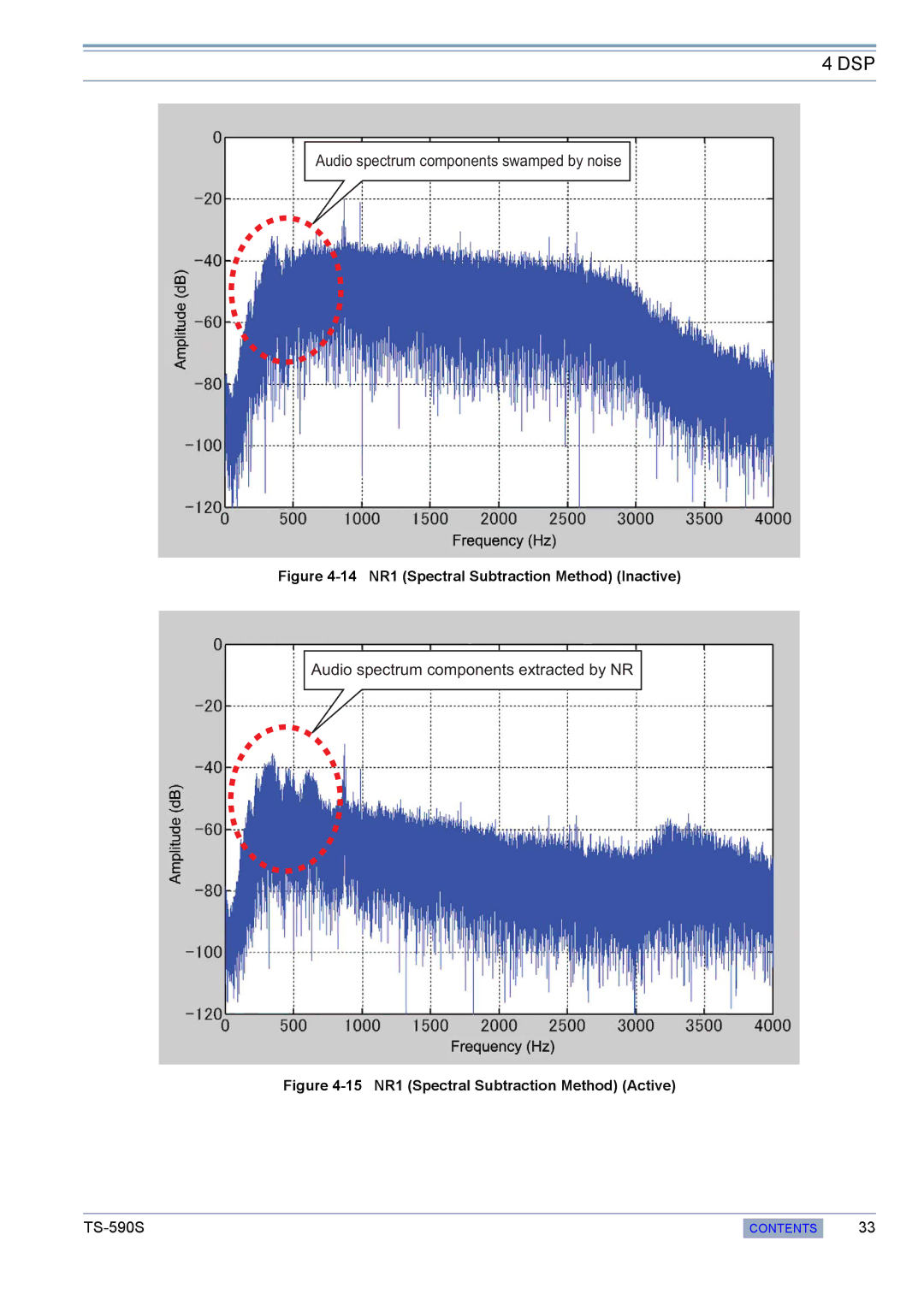
Audio spectrum components swamped by noise
Figure 4-14 NR1 (Spectral Subtraction Method) (Inactive)
Audio spectrum components extracted by NR
Figure 4-15 NR1 (Spectral Subtraction Method) (Active)
CONTENTS
33