9 OPTIONAL ACCESSORY
9.2Rectifier Circuit
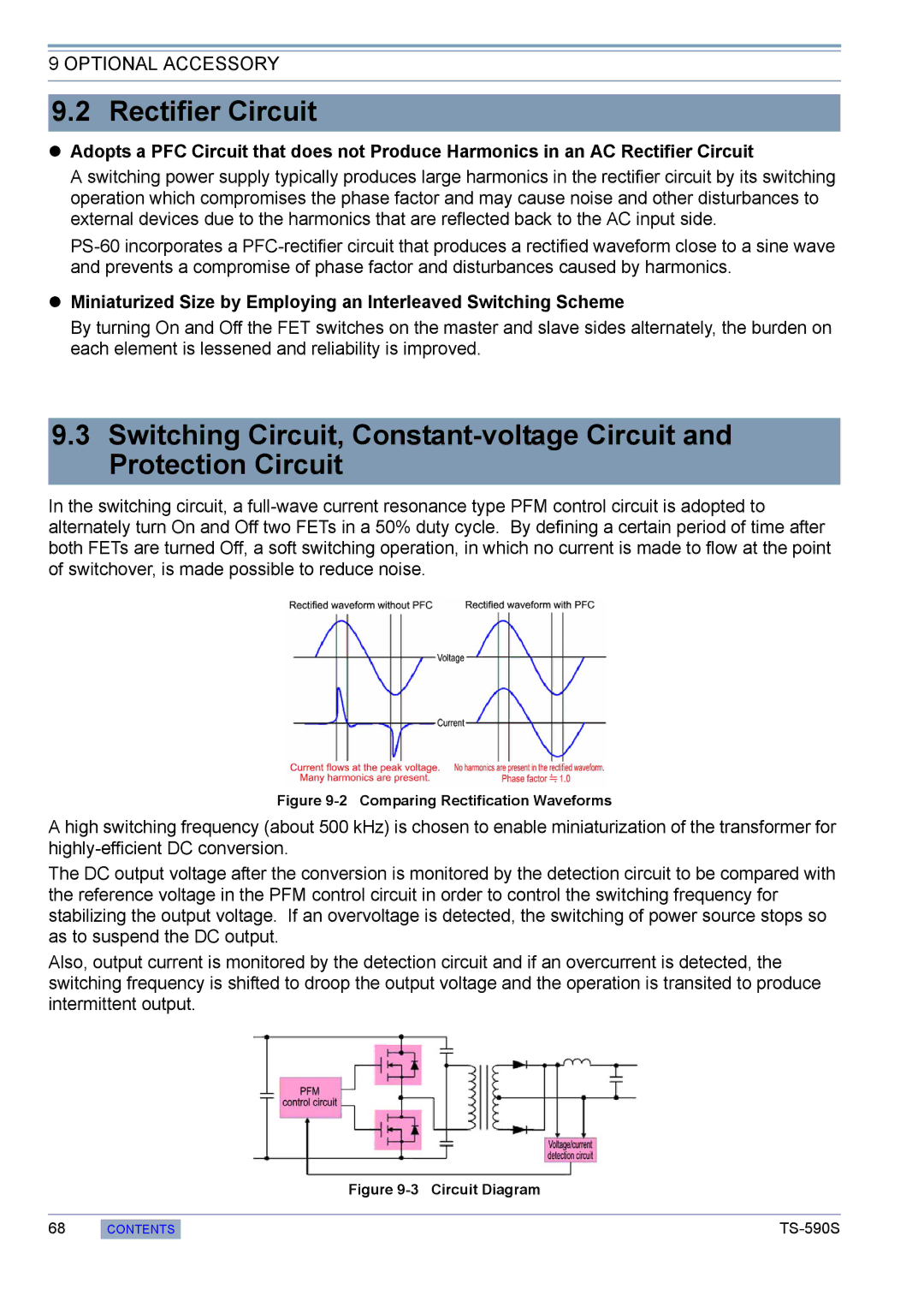
Adopts a PFC Circuit that does not Produce Harmonics in an AC Rectifier Circuit
A switching power supply typically produces large harmonics in the rectifier circuit by its switching operation which compromises the phase factor and may cause noise and other disturbances to external devices due to the harmonics that are reflected back to the AC input side.
Miniaturized Size by Employing an Interleaved Switching Scheme
By turning On and Off the FET switches on the master and slave sides alternately, the burden on each element is lessened and reliability is improved.
9.3Switching Circuit,
In the switching circuit, a
Figure 9-2 Comparing Rectification Waveforms
A high switching frequency (about 500 kHz) is chosen to enable miniaturization of the transformer for
The DC output voltage after the conversion is monitored by the detection circuit to be compared with the reference voltage in the PFM control circuit in order to control the switching frequency for stabilizing the output voltage. If an overvoltage is detected, the switching of power source stops so as to suspend the DC output.
Also, output current is monitored by the detection circuit and if an overcurrent is detected, the switching frequency is shifted to droop the output voltage and the operation is transited to produce intermittent output.
68
Figure 9-3 Circuit Diagram
CONTENTS |