G 44 1/4" |
|
| Installing Your Exhaust Hood |
Duct |
|
| Your Elmira range is equipped with a 350 CFM exhaust |
C 15 3/8" |
|
| fan located in the warming cabinet. This fan can be vented |
|
|
| |
|
|
| directly to the outside or, with the use of the #1442 Charcoal |
Nickel | D |
| Filter (included) can recirculate purified exhaust air into the |
62 1/4" |
| room. | |
Rail |
| ||
| M |
| Charcoal filter should be changed every six months. |
Nickel Rail | 64 1/4" |
| |
| N |
| See page 20 for Filter Cleaning and Replacement. |
| 68 1/4" |
|
|
Ventless Installation
|
|
|
|
| Remove the charcoal filter from the broiler pan and |
|
|
|
|
| remove plastic wrap. Remove the two screws holding |
BACK VIEW |
| the mesh filter in place with a #2 phillips or red square | |||
OF RANGE |
| screw driver. Insert the charcoal filter into mesh filter and | |||
| I |
|
|
| |
| 28 1/2" |
| replace the assembly. See figure 4 | ||
|
|
| |||
|
|
| L |
|
| 64 1/4" 68 1/4" | 29 | 1/2" | |
|
| |||
|
|
| ||
36 3/8" | 37 3/8" M | N |
| Figure 4 |
E | F |
|
|
|
|
| H | 30 1/2" |
|
|
|
|
|
|
|
|
|
|
|
|
|
| To increase efficiency of the charcoal filter system, fan air | |||
|
|
|
|
|
|
|
|
|
|
|
|
|
|
|
|
|
| A | should blow against the 45 degree vent deflector at rear of | ||
|
|
|
|
|
|
|
|
|
|
|
|
|
|
|
|
|
| ||||
|
|
|
|
|
|
|
|
|
|
|
|
|
|
|
|
|
| ||||
| Duct |
|
|
|
|
|
|
|
|
|
|
|
|
|
|
|
| stove. | |||
|
|
|
|
|
|
|
|
|
|
|
|
|
|
|
|
| 30 | 1/8" |
| ||
|
|
|
|
|
|
|
|
|
|
|
|
|
|
|
|
|
|
| |||
|
|
|
|
|
|
|
|
|
|
|
|
|
|
|
|
|
|
|
| ||
|
|
|
|
| C | 15 3/8" |
|
|
|
|
|
|
|
|
|
|
|
|
| ||
|
|
|
|
|
|
|
|
|
|
|
|
|
|
|
|
|
| Vented Installation | |||
|
|
|
|
|
|
|
|
|
|
|
|
|
|
|
|
|
|
|
| ||
|
|
|
|
|
|
|
|
|
|
| D |
|
|
|
|
| • Remove vent deflector on rear of stove if venting to the | ||||
|
|
|
|
|
|
|
|
|
|
| 62 1/4" |
|
|
|
|
| outside and seal screw holes. | ||||
|
|
|
|
|
|
|
|
|
|
|
|
|
| M |
|
|
|
|
| ||
|
|
|
|
|
|
|
|
|
|
|
|
|
|
|
|
|
|
| • If the exhaust hood is to be vented, the duct location | ||
|
|
| Nickel Rail |
| 64 1/4" |
|
|
| |||||||||||||
|
|
|
|
|
|
|
|
|
|
|
|
|
|
|
| N |
|
|
| must be installed in accordance with figure 3, page 7. | |
|
|
|
|
|
|
|
|
|
|
|
|
|
| 68 1/4" |
| Exhaust air must not be vented into a wall, ceiling, attic | |||||
|
|
|
| B |
|
|
|
|
|
|
|
|
|
| |||||||
|
|
| 29 1/2" |
|
|
|
|
|
|
|
|
|
|
|
|
|
| or a concealed space of a building. | |||
|
|
|
|
|
|
|
|
|
|
|
|
|
|
|
|
| |||||
|
|
|
|
|
|
|
|
|
|
|
|
|
|
|
|
|
|
|
| ||
|
|
|
|
|
|
|
|
|
|
|
|
|
|
|
|
|
|
|
| Note: Installation must be in accordance with local | |
|
|
|
|
|
|
|
|
|
|
|
|
|
|
|
|
|
|
|
| ||
|
| BACK VIEW |
|
|
|
|
|
|
|
| Figure 3 | and national building codes. Use only materials which | |||||||||
|
|
|
|
|
|
|
|
|
|
|
| conform to codes in effect. Disconnect power before | |||||||||
|
| OF RANGE |
|
|
|
|
|
|
|
|
|
| |||||||||
|
|
|
|
|
|
|
|
|
|
|
| ||||||||||
|
|
|
|
|
|
|
|
|
|
|
|
|
|
|
|
|
|
|
| doing any electrical work. Use only metal ducting, do | |
|
|
|
|
|
|
|
|
|
|
|
|
|
|
|
|
|
|
|
| not use plastic. Assemble securely so that in the event of | |
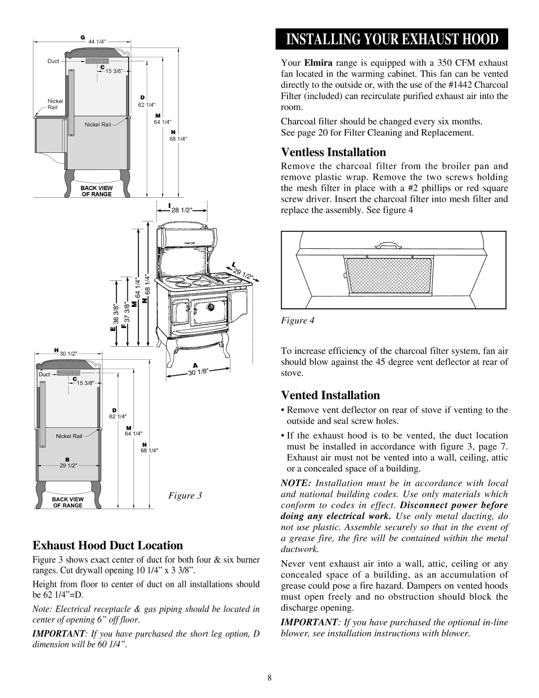
Exhaust Hood Duct Location |
| a grease fire, the fire will be contained within the metal | |||||||||||||||||||
| ductwork. | ||||||||||||||||||||
Figure 3 shows exact center of duct for both four & six burner | Never vent exhaust air into a wall, attic, ceiling or any | ||||||||||||||||||||
ranges. Cut drywall opening 10 1/4” x 3 3/8”. |
| ||||||||||||||||||||
| concealed space of a building, as an accumulation of | ||||||||||||||||||||
Height from floor to center of duct on all installations should | |||||||||||||||||||||
grease could pose a fire hazard. Dampers on vented hoods | |||||||||||||||||||||
be 62 1/4”=D. |
|
|
|
|
|
|
|
|
|
| must open freely and no obstruction should block the | ||||||||||
Note: Electrical receptacle & gas piping should be located in | discharge opening. | ||||||||||||||||||||
center of opening 6” off floor. |
| Important: If you have purchased the optional | |||||||||||||||||||
Important: If you have purchased the short leg option, D | blower, see installation instructions with blower. | ||||||||||||||||||||
dimension will be 60 1/4”. |
|
| |||||||||||||||||||
8