User Guide
Technical Support Sales Offices
Lantronix Corporate Headquarters
Technology Drive Irvine, CA 92618, USA Toll Free Phone Fax
Date Rev Firmware Comments
Table of Contents
Configuration via Telnet or Serial Port Setup Mode
Setup Mode Advanced Settings
Problems and Error Messages Technical Support
List of Figures
List of Tables
Chapter Summary
Using This Guide
Purpose and Audience
Remaining chapters in this guide include
Document Description
DeviceInstaller Online Help
Additional Documentation
Micro125 Integration Guide
Introduction
Capabilities
Applications
Addresses and Port Numbers
Configuration Methods
Protocol Support
Hardware Address
IP Address
Port Numbers
Required Information
Physically Connecting the Unit
Getting Started
10/100 Ethernet
Getting Started
To install DeviceInstaller
Using DeviceInstaller
Installing DeviceInstaller
Assigning an IP Address
DeviceInstaller provides a view of the units configuration
Accessing the Micro125 Using DeviceInstaller
Viewing the Current Configuration
To view the units current settings
Type
Comments
Device Family
Hardware Address
Setup Supports 230K Baud
Upgradeable
Configurable Pins
Firmware
Configuration Using Web Manager
Accessing Web-Manager Using DeviceInstaller
Web-Manager Login Window
Lantronix Web-Manager
Automatic IP Address Configuration
Network Configuration
Network Mode
Select Obtain IP address automatically
Enter the following as necessary
Static IP Address Configuration
Select Use the following IP configuration
To assign an IP address manually
To specify how data will be transmitted
Ethernet Configuration
Ethernet Settings Description
Auto Negotiate
Server Configuration
To configure the Micro125’s device server settings
Server Configuration Description Settings
Advanced Settings Description
Host List Configuration
To configure the Micro125’s host list
On the main menu, click Hostlist
Retry Settings Description
Channel 1 and Channel 2 Configuration
Retry Settings
Host Information
Channel Setting Description
Serial Settings
To configure the channel’s serial settings
Port Settings Description
Pack Control Settings Description
With Active Connect
Flush Input Buffer Settings Description
Flush Output Buffer Description Settings
With Passive Connect
Connection Settings TCP
To configure a channel’s TCP settings
Active Connection Mode Description Settings
Connect Protocol Setting Description
Passive Connection Mode Description Settings
Available fields, enter or modify the following information
Endpoint Configuration Description Settings
Common Option Settings Description
Disconnect Mode Settings Description
Inactivity Timeout
Connection Settings UDP
To configure a channel’s UDP settings
Check EOT Ctrl-D
Apply Settings
Datagram Mode Description Settings
Connection Protocol Description
Apply Defaults
Applying Settings
Configuration via Telnet or Serial Port Setup Mode
Accessing Setup Mode
Telnet Connection
Serial Port Connection
To establish a Telnet connection
Click OK. The following information displays
Exiting Setup Mode
To exit setup mode, utilize one of the following two options
This chapter explains how to configure the network settings
Setup Mode Server Configuration
Server Configuration Option
IP Address
Set DNS Server IP Address
Set Gateway IP Address
Netmask Number of Bits for Host Part
Standard IP Network Netmasks
Change Telnet/Web-Manager Password
Dhcp Name
Setup Mode Channel Configuration
Channels
Baudrate
Mode Option
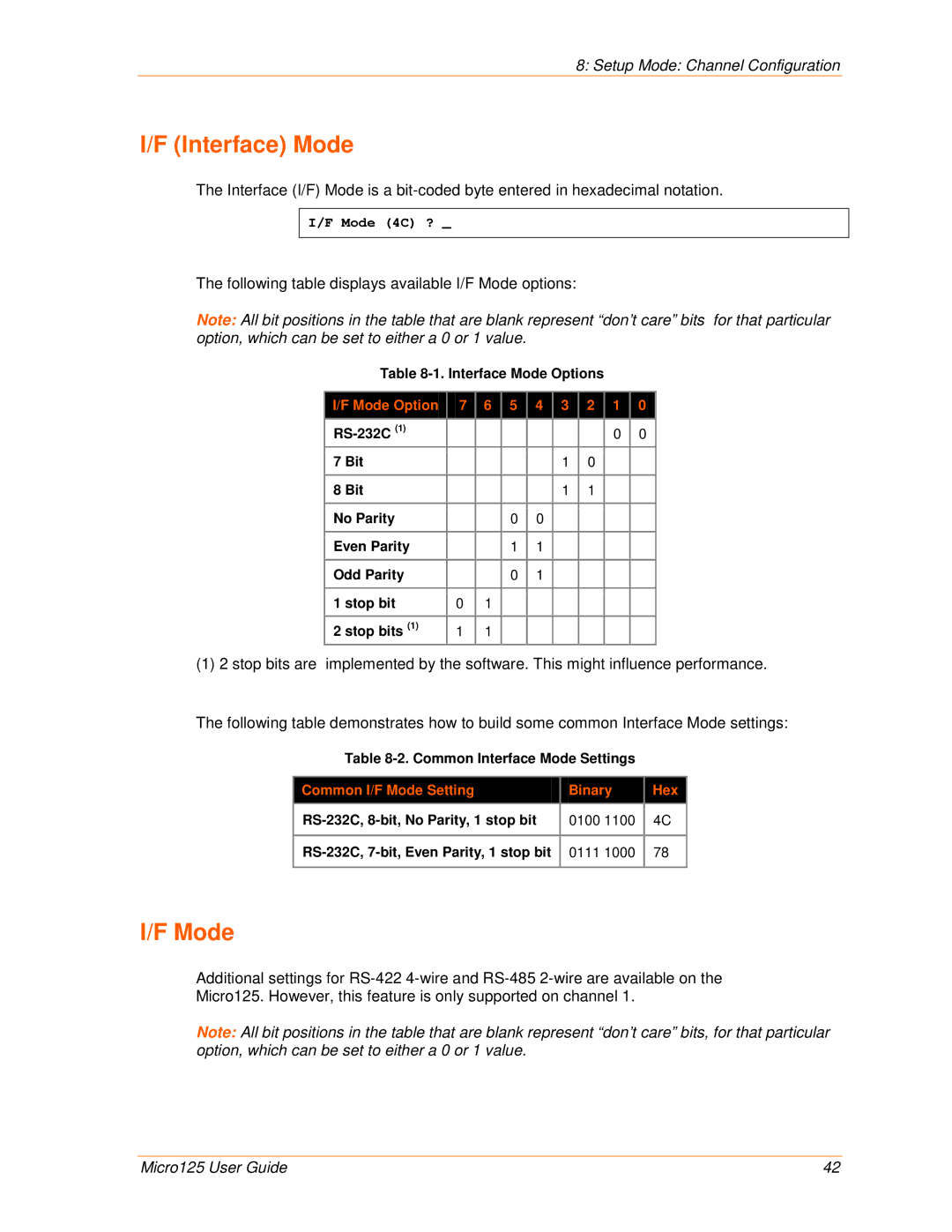
Interface Mode
Following table displays available I/F Mode options
Common I/F Mode Setting Binary Hex
Flow
Port Number
Use the following table to select flow control options
Connect Mode Options
Connect Mode
Enter Connect Mode options in hexadecimal notation
Connect Mode Option
Response
Active Startup
C28.10/12
Manual Connection Address Example
C121.2.4.5/1
C0.0.0.0/0
To enable the hostlist
Hostlist Option
Datagram Type
Modem Mode
Modem Mode Description
Datagram Type Description
Message Meaning
Modem Mode Messages
Full Verbose Command was executed without error
Network connection has been established
Send the Escape Sequence +++ in Modem Mode
Modem Mode Function Command
Remote IP Address
Show IP addr after Ring
Auto Increment Source Port
Remote Port
11. Disconnect Mode Options
Disconnect Mode Option
Flush Mode Buffer Flushing
Pack Control
Option
Trailing Characters
DisConnTime Inactivity Timeout
Packing Interval
Send Characters
Channel Port Password
Send Characters
Telnet Terminal Type
Default settings are listed below
Setup Mode Advanced Settings
Expert Settings Option
Device Details Settings Description
TCP Re-transmission Timeout
ARP Cache Timeout in Seconds
Disable Monitor Mode at Bootup
Enable Alternate MAC
Disable Telnet Setup
Security Settings Option
Disable Snmp
Select 6 to configure security settings
Disable Web Server
Disable Tftp Firmware Upgrade
Disable Port 77FE Hex
Disable Web Setup
Enable Enhanced Password
To configure AES encryption on the Micro125
Expert Settings Defaults
Default Settings Option
Channel 1 and Channel 2 Configuration Defaults
Channel Setting Default Configuration
Security Settings Defaults
Security Setting Default Configuration
Obtaining Firmware Reloading Firmware
Firmware Upgrades
Using Tftp Graphical User Interface
To download new firmware from a computer
Using Tftp Command Line Interface
Firmware Upgrades
To recover firmware
Entering Monitor Mode Using the Network Port
Monitor Mode
Entering Monitor Mode Using the Serial Port
Monitor Mode Commands
G0, G1, ....,Ge, Gf
Monitor Mode Commands
Command Command Name Function
S0, S1,...,Se, Sf
Response Meaning
Troubleshooting
Problems and Error Messages
Problem/Message Reason Solution
Troubleshooting
Caps Lock is not on
Correctly to make a good socket
Phone 800 422-7044 US Only 949
Technical Support
Technical Support US
Technical Support Europe, Middle East, and Africa
Conversion Table
Binary to Hexadecimal Conversions
Converting Binary to Hexadecimal
Decimal Binary Hex
Scientific Calculator