Manuals
/
Lennox International Inc
/
Household Appliance
/
Air Conditioner
Lennox International Inc
506510-01
installation instructions
Low Pressure Switch Operation
Models:
Dave Lennox Signature Collection XC17 Air Conditioner
506510-01
1
40
49
49
Download
49 pages
11.15 Kb
37
38
39
40
41
42
43
44
Install
3ROUTE Control Wires
Maintenance
Resetting LED Alert Codes
Side View Access View
Test Pins Function
Recovering
Leak Testing the System
New Outdoor Unit Placement
Operating Service Valves
Page 40
Image 40
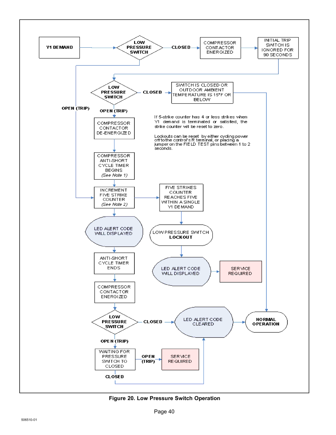
Figure 20. Low Pressure Switch Operation
Page 40
506510−01
Page 39
Page 41
Page 40
Image 40
Page 39
Page 41
Contents
Table of Contents
General
Shipping and Packing List
AIR Conditioner
Unit Dimensions − Inches mm and Parts Arrangement
Side View Access View
Model Number Identification
Base with Elongated Legs
Typical Unit Parts Arrangement
PLUMBING, Switches and Sensor Components
Control BOX
Operating Gauge Set and Service Valves
Using Manifold Gauge SET
Operating Service Valves
Torque Requirements
To Access Service Port
Operating Angle Type Service Valve
Operating Ball Type Service Valve
Reinstall Stem Cap
Recovering
Recovering Refrigerant from Existing System
New Outdoor Unit Placement
Clearance on ALL Sides Minimum Clearance Above Unit
Minimum Clearance Between TWO Units
Positioning Considerations
Stabilizing Unit on Uneven Surfaces
Elevating the Unit
Roof Mounting
Outside Unit Placement
Elevated Slab Mounting using Feet Extenders
Slab Mounting at Ground Level
Stabilizing Unit on Uneven Surfaces
Removing and Installing Panels
Access Panel Removal
Access and Louvered
Louvered Panel Installation
New or Replacement Line Set
Refrigerant Line SET
Line SET
Brazing
Flushing
Flushing the System
Uncased Coil Shown
Line SET and Indoor Coil 1
Equalizer Line Installation
Sensing Bulb Installation
Flushing Line SET and Indoor Coil 2
Leak Testing the System
Installing Isolation Grommets
Leak Test
Line SET and Indoor Coil
Evacuating
Evacuating the System
Size Circuit and Install Disconnect
2INSTALL Thermostat
Electrical
24VAC Transformer
3ROUTE Control Wires
4ROUTE High Voltage and Ground Wires
Typical XC17 Wiring
Main Control Jumpers and Terminals
Main Control AGE
Main Control Jumpers and Terminals
FAN
Field Control Wiring
Flat metal jumper
On−board link
Connections for Testing and Charging
Gauge SET
Servicing Units Delivered Void of Charge
Unit Start−Up
Indoor Coil
Airflow
Action
Weigh
Charge METHOD? Determine by
Requirements
Calculating System Charge for Outdoor Unit Void of Charge
Subcooling
Approach
Test and Charge Method
Operating and Temperature Pressures
HFC−410A Temperature Fahrenheit Psig
System Operation
Test Pins Function
Ambient Sensor Temperature / Resistance Range
High Discharge Sensor Temperature / Resistance Range
Sensor Temperature / Resistance Range
Resetting LED Alert Codes
Main Control LED Alert Codes
System LED Alert Codes
Alert Status
Compressor LED Alert Codes
Detected in RUN
High Pressure Switch Operation
Low Pressure Switch Operation
High Discharge Temperature Sensor Operation
Maintenance
Verifying Jumper Settings J2
FAN Motor Control and Start UP
Verifying LED Status Codes
LED Codes and Sequence of Operations
Fan Motor Board Unit LED Codes
Control Panel
Testing for External Power to Fan Control
Fan Motor Test
FAN Motor Surge Protection
Fan Motor Surge Protection Device
Cooling Mode
XC17 Start−Up and Performance Checklist
Start UP Checks
Subcooling
Top
Page
Image
Contents