|
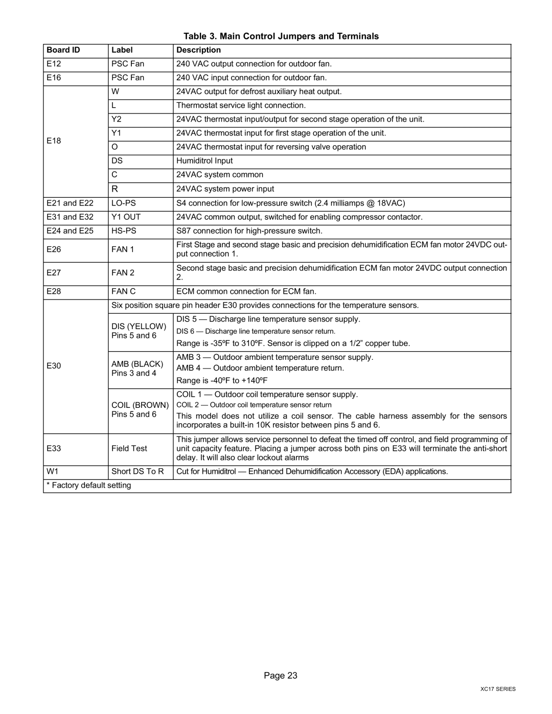
| Table 3. Main Control Jumpers and Terminals | |
|
|
| |
Board ID | Label | Description | |
|
|
| |
E12 | PSC Fan | 240 VAC output connection for outdoor fan. | |
|
|
| |
E16 | PSC Fan | 240 VAC input connection for outdoor fan. | |
|
|
| |
| W | 24VAC output for defrost auxiliary heat output. | |
|
|
| |
| L | Thermostat service light connection. | |
|
|
| |
| Y2 | 24VAC thermostat input/output for second stage operation of the unit. | |
|
|
| |
| Y1 | 24VAC thermostat input for first stage operation of the unit. | |
E18 |
|
| |
O | 24VAC thermostat input for reversing valve operation | ||
| |||
|
|
| |
| DS | Humiditrol Input | |
|
|
| |
| C | 24VAC system common | |
|
|
| |
| R | 24VAC system power input | |
|
|
| |
E21 and E22 | LO−PS | S4 connection for low−pressure switch (2.4 milliamps @ 18VAC) | |
|
|
| |
E31 and E32 | Y1 OUT | 24VAC common output, switched for enabling compressor contactor. | |
|
|
| |
E24 and E25 | HS−PS | S87 connection for high−pressure switch. | |
|
|
| |
E26 | FAN 1 | First Stage and second stage basic and precision dehumidification ECM fan motor 24VDC out- | |
put connection 1. | |||
|
| ||
|
|
| |
E27 | FAN 2 | Second stage basic and precision dehumidification ECM fan motor 24VDC output connection | |
2. | |||
|
| ||
|
|
| |
E28 | FAN C | ECM common connection for ECM fan. | |
|
|
| |
| Six position square pin header E30 provides connections for the temperature sensors. | ||
|
|
| |
| DIS (YELLOW) | DIS 5 | |
| DIS 6 | ||
| Pins 5 and 6 | ||
|
| ||
|
| Range is −35ºF to 310ºF. Sensor is clipped on a 1/2" copper tube. | |
|
|
| |
| AMB (BLACK) | AMB 3 | |
E30 | AMB 4 | ||
| Pins 3 and 4 | ||
| Range is −40ºF to +140ºF | ||
|
| ||
|
|
| |
|
| COIL 1 | |
| COIL (BROWN) | COIL 2 | |
| Pins 5 and 6 | This model does not utilize a coil sensor. The cable harness assembly for the sensors | |
|
| incorporates a built−in 10K resistor between pins 5 and 6. | |
|
|
| |
|
| This jumper allows service personnel to defeat the timed off control, and field programming of | |
E33 | Field Test | unit capacity feature. Placing a jumper across both pins on E33 will terminate the anti−short | |
|
| delay. It will also clear lockout alarms | |
|
|
| |
W1 | Short DS To R | Cut for Humiditrol Enhanced Dehumidification Accessory (EDA) applications. | |
|
|
| |
* Factory default setting |
| ||
|
|
| |
Page 23
XC17 SERIES
