System Operation
![]() IMPORTANT
IMPORTANT
Some scroll compressor have internal vacuum protector that will unload scrolls when suction pressure goes below 20 psig. A hissing sound will be heard when the compressor is running unloaded. Protector will reset when low pressure in system is raised above 40 psig. DO NOT REPLACE COMPRESSOR.
The Main Control provides the following system functions:
SCompressor anti−short−cycle delay.
SHigh and low pressure switches
SAmbient andDischargeLineTemperatures Monitoring and Protection.
SFive strikes lockout safety feature for High/Low Pressure Switches and High Discharge Line Temperature. See Figures 19, 20 and 21 feature function.
COMPRESSOR ANTI−SHORT CYCLE DELAY The Main Control protects the compressor from:
SShort cycling (five minutes) when there is initial power up
SInterruption in power to the unit
SHigh or low pressure switch or discharge line sensor trips
SDelay after Y1 demand is removed.
The anti−short timer in the outdoor control is 5 minutes. To override timer when active or inactive − place jumper on the field test pins between 1 and 2 seconds.
Resetting Anti−Short Cycle Delay
The FIELD TEST pins (E33) on the Main Control can be jumpered between 1 to 2 seconds to bypass delay.
HIGH AND LOW PRESSURE SWITCHES
The unit’s reset pressure switches LO PS (S4) and HI PS (S87) are factory−wired into the Main Control on the LO−PS and HI−PS terminals, there locations are illustrated on Page 3. Sequence of operations for both pressure switches are provided in Figures 19 and 20.
HIGH DISCHARGE LINE TEMPERATURE SENSOR (RT28)
The high discharge line temperature sensor location is illustrated on Page 3. This sensor’s sequence of operations is provided in Figure 21.
High Discharge Line Sensor Open/Shorted Event
Condition
Discharge sensor open / short fault is ignored during initial 90−seconds of compressor run time. After that, if discharge temperature sensor is detected open or short, the control will de−energize all the outputs and anti−short cycle timer is started. Discharge sensor faulty alert LED code will be displayed.
OUTDOOR AMBIENT TEMPERATURE (RT13)
If the outdoor ambient temperature sensor detected a open, or out of range −40ºF to +140ºF (−40ºC to 60ºC) then LED alert codes are displayed, however cooling operation will continue. See Table 9 for LED alert codes for the ambient sensor. Location of outdoor ambient temperature sensor is illustrated on Page 3.
COIL TEMPERATURE SENSOR
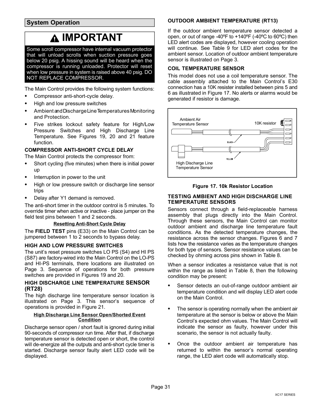
This model does not use a coil temperature sensor. The cable assembly attached to the Main Control’s E30 connection has a 10K resister installed between pins 5 and 6 as illustrated in Figure 17. No alerts or alarms would be generated if resistor is damage.
Ambient Air | 10K resistor |
Temperature Sensor | |
High Discharge Line |
|
Temperature Sensor |
|
Figure 17. 10k Resistor Location
TESTING AMBIENT AND HIGH DISCHARGE LINE TEMPERATURE SENSORS
Sensors connect through a
When a sensor indicates a resistance value that is not within the range as listed in Table 8, then the following condition may be present:
SSensor detects an out−of−range outdoor ambient air temperature condition and will display LED alert code on the Main Control.
SThe sensor is operating normally when the ambient air temperature at the sensor is below or above the Main Control’s expected ohm values. The Main Control will indicate the sensor as faulty, however under this scenario, the sensor is not actually faulty.
SOnce the outdoor ambient air temperature has returned to within the sensor’s normal operating range, the LED alert code will automatically stop.
Page 31
XC17 SERIES